

Metal cable runs
Outside the cabinets, beyond a distance of 3 m, the ducts must be metal. These cable runs must have electrical continuity from end to end via fish plates or foils.
It is very important to set up connections using fish plates or foils rather than using a braid or even a round conductor. These cable runs must be connected in the same way to the cabinet and machine connections, if necessary after scraping away the paint in order to ensure contact.
An accompanying cable will only be used when there is no other solution.
Example: Use of a metallic duct
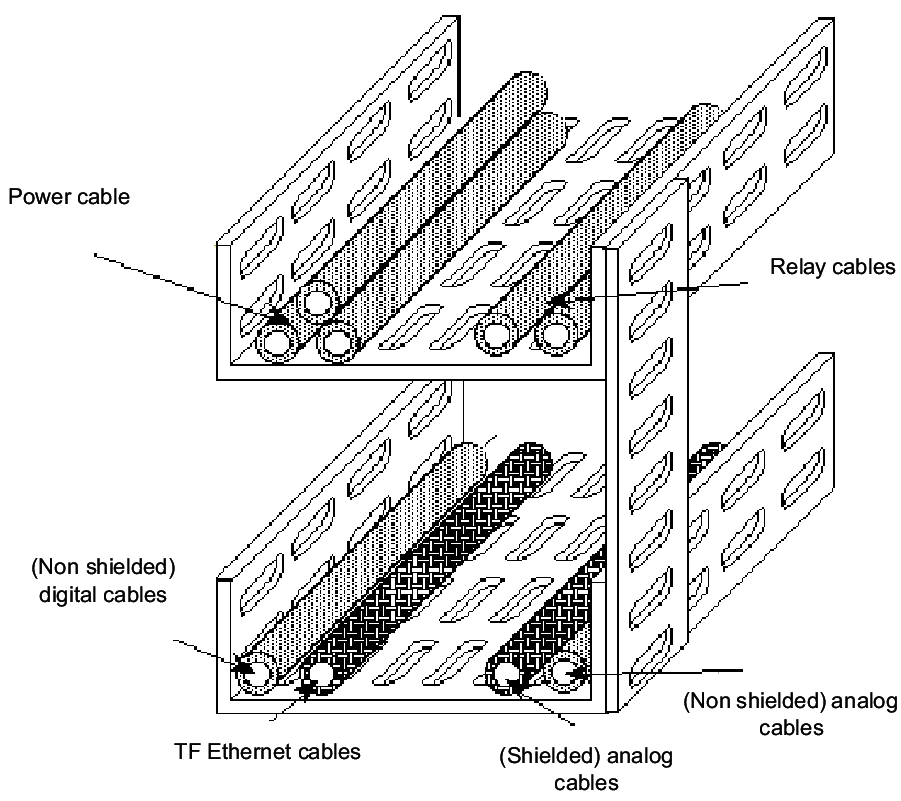
Non-shielded cables must be fixed in the corners of the ducts as shown in the illustration below.
Future developments
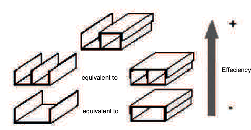
Bear in mind future developments. Vertical separation in the duct avoids mixing incompatible cables. A metal cover on the signals half duct is desirable. You must be aware that a complete metal cover on the duct does not improve the EMC.
Efficiency of the various types of ducts
Transparent Factory
For Transparent Factory, as for each communication network, an initial maximum limit for segment length (without repeater) must be observed. This limit of 100 metres, can only be achieved if installation conditions are satisfactory with regard to the EMC (especially: cables placed in metal ducts with end to end electrical continuity connected to frame ground mesh and to earth system).
It is therefore necessary to define a maximum theoretical length for electromagnetic compatibility. This second limit is theoretical and is used to optimize installation conditions and must be observed at the same time as the previous limit.
The theoretical EMC length is 400 meters for Transparent Factory.
Separating the cables according to their type
Except when it is not possible, two metal ducts will be used:
one reserved for power, relays and variators
the other for signal cables (sensors, data, telecoms..).
These two ducts can be in contact if they are shorter than 30 m. From 30 to 100 m they shall be spaced 10 cm apart, either side by side or one above the other.
Example of installation with 2 ducts
All these particular limits come from the same EMC Theoretical Length, or "ETL".
To reach this ETL it is assumed that the following two optimum conditions have been fulfilled:
a second duct, at least 30 cm away, is reserved for power and relay cables,
the ducts are not filled to more than 50% of their capacity.
Ki Coefficient
Depending on the type of communication network this value can be different.
Everytime one of both conditions is not fulfilled from end to end and in order to observe electromagnetic compatibility, a coefficient must be assigned to the physical duct length. These Ki coefficients, defined in the table below, measure the decrease of the protective effect. The resulting authorized length will then be less than the ETL.
Similarly, in the case of a single duct for power and signal cables, the coefficient will take into account the lack of a metal separation or metal covering on the signal half duct.
Summary table
Symbol |
Condition |
Illustration |
Coefficient |
Total length (1) |
|---|---|---|---|---|
Ki |
ETL x 1/Ki |
|||
K50 |
Single duct filled to 50% or more |
2 |
200 m |
|
K10 |
Ducts 10 cm apart (instead of 30 cm) |
 |
2 |
200 m |
K6 |
Single duct or 2 contiguous ducts with separation and cover on the signal half duct |
 |
4 |
100 m |
K8 |
Single duct or 2 contiguous ducts without cover on the signal half duct |
 |
6 |
60 m |
K0 |
Single duct or 2 contiguous ducts without separation |
 |
12 |
30 m |
(1) Maximum total length if it's the unique condition against (with ETL = 400m)