Mounting the Module in the Quantum PLC Backplane
Original instructions
Before you Begin
Locate the backplane in which you will mount the module. Ensure that an open slot is available.
NOTE: The module can be installed only in a local backplane.
NOTE: Ensure when installing the module that it does not exceed the Quantum backplane power requirements as specified in Quantum using EcoStruxure™ Control Expert, Hardware Reference Manual.
Backplane Slot Replacement
You may place the module in any slot on the backplane. You do not need to place it next to other modules.
Tools Required
You will need one medium-size, Phillips-head screw driver.
Mounting the Module in the Backplane
Perform the following steps to mount the module.
Step
Action
1
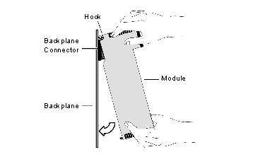
Holding the module at an angle, mount it on the two hooks located near the top of the backplane. The following figure shows the correct way to hold the module.
2
Swing the module down so its connector engages the backplane connector.
3
Using a Phillips-head screw driver, tighten the screw at the bottom of the module between 2 and 4 in-lbs or between .22 and .45 Newton meters of torque.
Grounding the Module
The module is grounded upon installation in the Quantum PLC backplane. For instructions on grounding the backplane, see Quantum using EcoStruxure™ Control Expert, Hardware Reference Manual.
NOTE: If you connect the module to the Ethernet hub or switch using a shielded cable, the cable is also grounded. Elsewhere in this guide is a discussion of cabling schemes and recommendations Cabling Schemes, as well as instructions for connecting the module to an Ethernet network Connecting the Cable.