|
|
Original instructions
|

|
Bit
|
Data Type
|
|
|---|---|---|
|
%I
|
%IW
|
|
|
1
|
%I1
|
%IW1.15
|
|
2
|
%I 2
|
%IW1.14
|
|
...
|
||
|
16
|
%I16
|
%IW1.0
|
|
17
|
%I17
|
%IW2.15
|
|
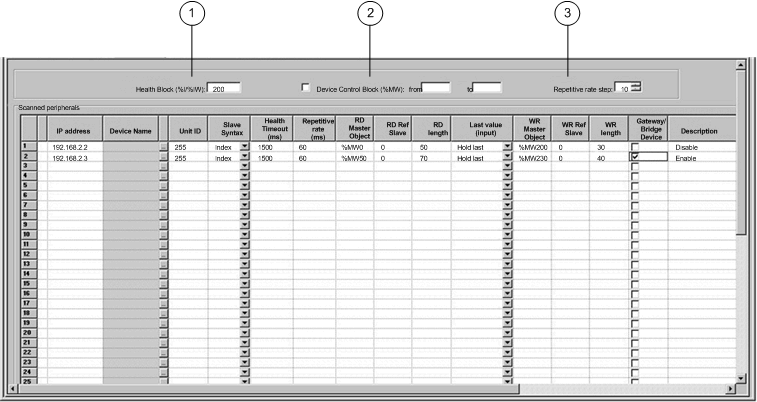
Parameter
|
Description
|
Example
|
|---|---|---|
|
Entry #
|
This is the first column; it has no name.
Valid range: 1 ... 128
Each entry represents an I/O Scanning exchange on the network.
|
|
|
IP address
|
This is the IP address of the scanned Ethernet slave device.
|
192.168.1.100
|
|
Device Name
|
To configure a device (Advantys island or DTM), click the ... button to open the Property box to start the device configuration software.
For an introduction to this procedure for Advantys, go here.
For an introduction to this procedure for DTMs, go to FDT Container.
NOTE: While the Property box is open, I/O scanning cannot be edited. |
MySTB1 or Master_PRM_DTM_10
|
|
Unit ID
|
This field associates the slave address of the device connected to an Ethernet/Modbus gateway with the IP address of that gateway:
|
255
|
|
Slave Syntax
|
Use this drop-down menu to pick the way RD Ref Slave and WR Ref Slave values are displayed. There are 4 types of display available:
|
Index (default value)
|
|
Health Timeout (ms)
|
This field sets the maximum interval between the responses from a remote device. After this time period expires, the received data is invalid. The Health Timeout should be longer than the Repetitive rate time (ms).
For a Quantum NOE Ethernet module, it also should be longer than the CPU scan time.
For the Health Timeout:
|
1500 ms
|
|
Repetitive rate (ms)
|
The rate at which data is scanned, from 0...65535 in multiples of the Repetitive Rate Step:
NOTE: Unity Pro is the former name of Control Expert for version 13.1 or earlier. |
60 ms
|
|
RD Master Object*
|
Destination address in the master PLC where, from each device, newly read information is stored
|
%mw10
|
|
RD Slave Ref.**
|
Source address index in the slave/remote device
|
The format of this value depends on the Slave Syntax:
|
|
RD length
|
Number of words to read
|
10
|
|
Last value (Input)
|
This field configures the behavior of inputs in the event of an access error in relation to the remote device (for example: inoperative network or device power supply, etc.):
|
Hold last
NOTE: When you select hold last in a 140 CPU 651 •0 coprocessor, the input data may fall back to 0 when the I/O scanner health bits are NOT OKAY. Confirm that the I/O scanner health bits are valid (OK=1) before removing the Ethernet cable to maintain hold last value. |
|
WR Master Object*
|
Source address of the master PLC whose data is being written into the slave/remote device.
Write operations are always performed at the word level.
|
%mw20
|
|
WR Slave Ref.**
|
The address of the first word written into the slave/remote device.
|
The format of this value depends on the Slave Syntax:
|
|
WR length
|
Number of words to be written
|
10
|
|
Gateway/Bridge Device
|
To allow slower TCP/IP network devices (i.e., gateways and bridges) to be compatible with the I/O Scanner:
|
|
|
Description
|
Additional information
|
|
|
*Master refers to the client PLC that makes the request.
**Slave refers to the server from which data is read or to which data is written.
|
||