Addressing
Original instructions
Flat Addressing
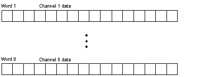
This module requires nine contiguous, 16-bit words-eight for input data and one for channel status. The data words formats are as follows.
The following shows the word 9 register.
NOTE: Count stops at 4095.
NOTE: The undervoltage for this module is 0.5 - 0.7 V.
NOTE: The broken wire detect is set at 2.0 mA.
Topological Addressing
Topological addresses for the 140 ACI 030 00 Input Module:
Point
I/O Object
Comment
Input 1
%IW[\b.e\]r.m.1
Value
%I[\b.e\]r.m.1.1
Broken wire or under voltage
• • •
Input 8
%IW[\b.e\]r.m.8
Value
%I[\b.e\]r.m.8.1
Broken wire or under voltage
Status Word
%IW[\b.e\]r.m.9
Status of input channels
Used abbreviations: b = bus, e = equipment (drop), r = rack, m = module slot.
IODDT
The 140 ACI 030 00 Input Module uses the T_ANA_IN_VE IODDT:
IODDT Name
Object
Data Type
Name
T_ANA_IN_VE
%CH[\b.e\]r.m.c
ANA_IN_VWE
userdefined
%IWr.m.c.0
Int
.VALUE
%Ir.m.c.1
Bool
.ERROR
Used abbreviations: r = rack, m = module slot, c = channel, b = bus, e = equipment (drop).
Bus and Drop default to 1 if not specified and can be left off.
NOTE: In Quantum IODDTs for analog modules and expert modules the data type Bool is used for %I and %Q.
I/O Map Status Byte
The I/O map status byte is used by the 140 ACI 030 00 Input Module as follows.