|
Specifications
|
|
|
Original instructions
|
|
Module Type
|
16 IN (2 groups x 8 points)
8 OUT (2 groups x 4 points)
|
|
External Power
|
85 ... 132 VAC required for output groups
|
|
Power Dissipation
|
5.5 W + 1.1 V x Total module load current
|
|
Bus Current required
|
250 mA
|
|
I/O map
|
1 input word
0.5 output word
|
|
Fault Detection
|
Input: None
Output: Blown fuse detect, loss of field power.
|
|
50 Hz
|
ON: 85 ... 132 VAC (11.1 mA max)
OFF: 0 ... 20 VAC
|
|
60 Hz
|
ON: 79 ... 132 VAC (13.2 mA max)
OFF: 0 ... 20 VAC
* Do not use outside the 47 ... 63 Hz range
|
|
Maximum Allowable Leakage Current from an External Device to be recognized as an OFF Condition.
|
2.1 mA
|
|
50 Hz
|
14.4 kohms capacitive
|
|
60 Hz
|
12 kohms capacitive
|
|
Continuous
|
132 VAC
|
|
10 s
|
156 VAC
|
|
1 Cycle
|
200 VAC
|
|
OFF - ON
|
Min: 4.9 ms. Max: 0.75 line cycle.
|
|
ON - OFF
|
Min: 7.3 ms. Max: 12.3 ms.
|
|
Continuous
|
85 ... 132 VDC
|
|
10 sec
|
156 VDC
|
|
1 Cycle
|
200 VDC
|
|
ON State Drop / Point
|
1.5 VDC
|
|
Each Point
|
4 A continuous
|
|
Each Group
|
4 A continuous
|
|
Per Module
|
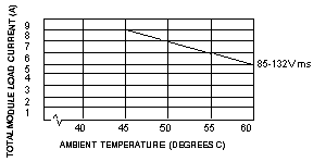
8 A continuous (see chart below for derating above 50 degree)
|
|
OFF State Leakage / Point
|
2 mA @ 115 VDC
|

|
One Cycle
|
30 A per point, 45 A per group
|
|
Two Cycle
|
20 A per point, 30 A per group
|
|
Three Cycle
|
10 A per point, 25 A per group
|
|
Min. Load Current
|
5 mA
|
|
OFF - ON / ON - OFF
|
0.5 of one line cycle max.
|
|
Applied DV / DT
|
400 V / micro sec
|
|
Group to Group
|
1000 VAC for 1 minute
|
|
Input or Output to Bus
|
1780 VAC for 1 minute
|