|
Specifications
|
|
|
Original instructions
|
|
Module Type
|
8 OUT (Normally Open / Normally Closed)
|
|
External Power
|
Not required for this module
|
|
Power Dissipation
|
2.75 W + 0.5 W x input points ON
|
|
Bus Current required (Module)
|
560 mA
|
|
I/O map
|
0.5 output word
|
|
AC
|
20 ... 250 VAC
|
|
DC
|
5 ... 30 VDC
30 ... 150 VDC (reduced load Current)
|
|
Each Point
|
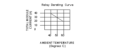
2 A max. @ 250 VAC @ 60 degrees C ambient, resistive load, 5A @ 40°C : see the derating curve below
2 A Tungsten lamp load
3 A @ a power factor of 0.4
1/4 hp @ 125 / 250 VAC
|
|
Each Point (30 ... 150 VDC)
|
300 mA (restive load)
100 mA (L/R = 10 msec)
|
|
Maximum module Current
|
40 A (see the derating curve below)
|
|
Surge Current (max.)
|
20 A capacitive load @ t = 10 ms
|

|
Minimum Load Current
|
50 mA
Note: Minimum load Current if the contact is used at rated loads of 5 ... 150 VDC or 20 ... 250 VAC
|
|
OFF State Leakage
|
< 100 μA
|
|
Output to Output
|
1780 VAC rms for one minute
|
|
Field to Bus
|
1780 VAC rms for one minute
2500 for one minute
|
|
OFF - ON
|
10 ms (max.)
|
|
ON - OFF
|
20 ms (max.)
|
|
Relay type
|
Form C, NO / NC contacts
|
|
Contact Protection
|
Varistor 275 V (internal)
|
|
Mechanical Operations
|
10,000,000
|
|
Electrical Operations
|
200,000 (resistive load @ max. Voltage and Current)
|
|
Electrical Operations (30 ... 150 VDC) (see note below)
|
100,000 @ 300 mA (resistive load)
50,000 @ 500 mA (resistive load)
100,000 @ 100 mA (L/R = 10 msec)
100,000 Interposing Relay (Westinghouse Style 606B, Westinghouse type SG, Struthers Dunn 219 x 13 XP)
|
|
Switching Capability
|
500 VA (reistive load)
|
|
Internal
|
None
|
|
External
|
User installed per local and national electrical codes
|