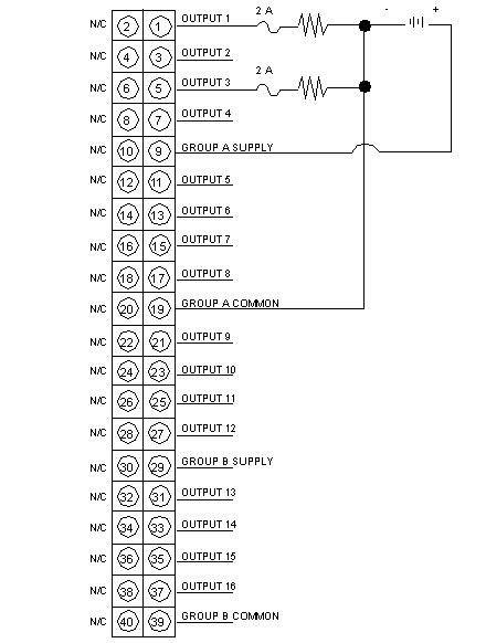
Wiring Diagram
Original instructions
Illustration
The following figure shows the 140 DDO 843 00 wiring diagram.
NOTE: N / C = Not Connected
NOTE: When field wiring the I/O module, the maximum wire size that should be used is 1-14 AWG or 2-16 AWG; the minimum size is 20 AWG.
If GROUP A SUPPLY or GROUP B SUPPLY are supplied and GROUP A COMMON or GROUP B COMMON are not connected, the state of the digital output channels of the corresponding group can be “1”, regardless of the state specified via the user program.
WARNING
UNINTENDED EQUIPMENT OPERATION
  • Ensure that GROUP A COMMON and GROUP B COMMON are always properly connected.
  • Verify that the terminals for GROUP A COMMON and GROUP B COMMON are tightened with the tightening torque of 7.0 N.m.
Failure to follow these instructions can result in death, serious injury, or equipment damage.
Each output group is equipped with an internal, replaceable 8 A fuse (250 V, 5x20 mm, Time Delay/Slow Blow).
The individual outputs must be fused separately.
CAUTION
INCORRECT OR MISSING FUSING
Provide a separate, external 2 A fuse for each individual output.
Failure to follow these instructions can result in injury or equipment damage.