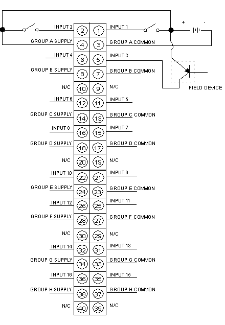
The following figure shows the 140 DDI 841 00 wiring diagram.
NOTE: N / C = Not Connected
NOTE: The module reads 0V if the polarity is reversed i.e. digital input is off if zero volt is given in place of 24V input channel.
NOTE: When field wiring the I/O module, the maximum wire size that should be used is 1-14 AWG or 2-16 AWG; the minimum size is 20 AWG.
NOTE: The tightening torque must be between 0.5áNm and 0.8áNm.
