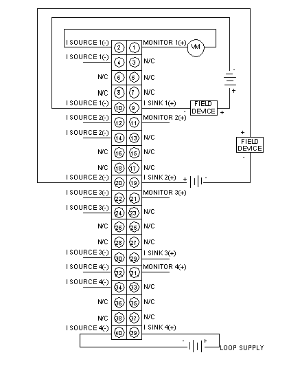
The following figure shows the wiring diagram for the 140 ACO 020 00 module.
External Wiring Recommendation
-
The user supplies the current and voltage sources (installation and calibration of fuses are at the discretion of the user).
-
Use shielded signal cable. In noisy environnements, twisted shielded cable is recommended.
-
Shielded cables should be connected to the PLC’s ground.
-
-
Unused channels indicate broken wire status unless wired to the loop supply, as shown on Channel 4. In this example, loop supply must be 30 V or less
-
The wiring example shows Channel 1 acting as a current sink and Channel 2 acting as a current source for their respective field devices.
-
N / C = Not Connected.
NOTE: VM is an optional voltmeter that can be connected to read voltage that is proportional to the current. Wiring to this terminal is limited to 1 meter maximum.
NOTE: When field wiring the I/O module, the maximum wire size that should be used is 1-14 AWG or 2-16 AWG; the minimum size is 20 AWG.
NOTE: The tightening torque must be between 0.5 Nm and 0.8 Nm.
 WARNING