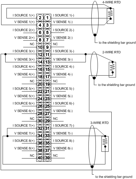
The following figure shows the wiring diagram of the 140 ARI 030 10.
External Wiring Recommendation
The module is calibrated per:
IEC Publication 751 for platinum RTDs: 100Ω @ 0 degrees C, TCR (α) = 0.00385Ω/Ω/degrees C.
DIN 43760 for nickel RTDs
American Platinum RTDs: 100Ω @ 0 degrees C, TCR (α) = 0.00392Ω/Ω/degrees C
NOTE: When field wiring the I/O module, the maximum wire size is 1-14 AWG or 2-16 AWG; the minimum size is 20 AWG.
NOTE: The tightening torque must be between 0.5 Nm and 0.8 Nm.
