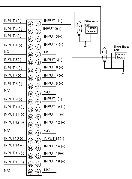
Wiring diagram for the 140 ACI 040 00 Module.
External Wiring Recommendations
-
The user supplies the current and voltage sources (installation and calibration of fuses are at the discretion of the user).
-
Use shielded signal cable. In noisy environnements, twisted shielded cable is recommanded.
-
Shielded cables should be connected to the PLC’s ground.
-
-
The maximum channel to channel working voltage cannot exceed 30 Vdc.
-
N / C = Not connected.
NOTE: When field wiring the I/O module, the maximum wire size that should be used is 1-14 AWG or 2-16 AWG; the minimum size is 20 AWG.
NOTE: The tightening torque must be between 0.5 Nm and 0.8 Nm.
