The following information describes how the data exchanged between the 140 SAI 940 00S module and the processor module are mapped.
Except for the health word, the data described here are transferred from the 140 SAI 940 00S module using the Quantum global backplane communication access mechanism which is common to all Quantum modules.
NOTE:
13 words are necessary for this module:
-
8 words dedicated to channel values, to obtain a full scale value each analog value have to be mapped on an UINT variable.
-
1 word dedicated to errors and warnings
-
3 words used by the module (module status, exchange number, CRC)
-
1 health word (this word is accessible by the processor module only)
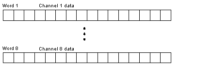
The following diagram shows the register of words 1 to 8. On word 1, you read the analog value sampled by channel 1, and so on.
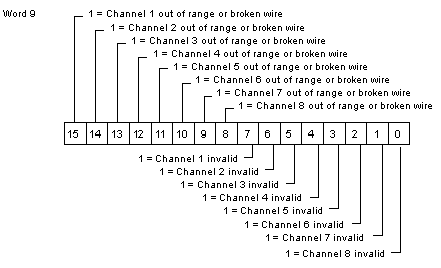
The following diagram shows the register of word 9. If bit 15 is set to 1, it means that channel 1 is out of range. If bit 7 is set to 1, it means that channel 1 is invalid. See the following diagram for the other channels.
Bit 15 to bit 8:
These 8 bits are set to 1 if the input current of the corresponding channel is out its functional limits (under 3.75 mA or over 20.25 mA).
Bit 7 to bit 0:
These 8 bits are set to 1 if internal diagnostics detects an invalid channel inside the module.
Words 10, 11 and 12 are used by the module for internal checking.
-
module status: reserved for future use
-
Exchange number: serial number of the set of data
-
Cyclic Redundancy Check (CRC): function used to detect errors after transmission
The health word is an extra system control generated by the processor module, using the data read from the input module.
Any of these errors activates the health word:
-
invalid channel (activates only the corresponding bit of the health word)
-
out of range current on channel (activates only the corresponding bit)
-
CRC
-
incorrect exchange number
If an unhealthy input is detected (if a bit on word 13 is set to 0), the value of the corresponding channel is set to 0 (word 1 to 8) except in case of out of range (the out-of-range value is not set to zero).
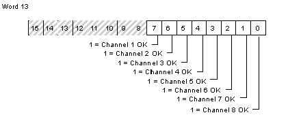
The following diagram shows the register of word 13.
Bit 15 to bit 8:
Those bits are not used in word 13.
Bit 7 to bit 0:
These 8 bits are set to 1 when no error is detected.
Topological addresses for the 140 SAI 940 00S Input Module.
|
Point
|
I/O Object
|
Comment
|
|
Input 1
|
%IWr.m.1
|
Analog value
|
|
%Ir.m.1.1
|
Invalid channel
|
|
%Ir.m.1.2
|
Out of range or broken wire
|
|
%Ir.m.1.3
|
Health bit
|
|
• • •
|
|
Input 8
|
%IWr.m.8
|
Analog value
|
|
%Ir.m.8.1
|
Invalid channel
|
|
%Ir.m.8.2
|
Out of range or broken wire
|
|
%Ir.m.8.3
|
Health bit
|
|
Module Status and Exchange number
|
%IWr.m.9.2
|
(internal use)
|
|
CRC LSW
|
%IWr.m.9.3
|
Less significant word of 32-bit CRC
(internal use)
|
|
CRC MSW
|
%IWr.m.9.4
|
Most significant word of 32-bit CRC
(internal use)
|
|
Health word
|
%IWr.m.9.5
|
|
Used abbreviations: r = rack, m = module slot.