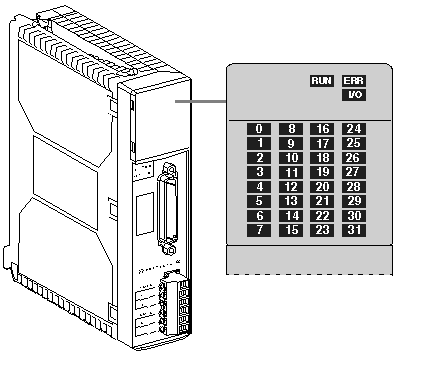
The safety modules are fitted with LED allowing module and channel status to be displayed.
They are:
The following diagram shows the safety module display screen:
Depending on their status (on, flashing or off) the three LEDs located on each module provide information on the operational state of the module:
-
The green RUN LED: indicates that the module is operational.
-
The red ERR LED: indicates an internal module fault or a fault between the module and the rest of the configuration.
-
The red I/O LED: indicates an external fault.
-
LEDs 0 to 27 indicate the status of the safety system:
-
0 to 11: status of SS ESD or PS (-) channel contacts
-
12 to 23: status of SS ESD or PS (+) channel contacts
-
24: reactivation input status
-
25: feedback loop status
-
26: safety relay control status
-
27: supply present on the safety system, safety system diagnostics
-
LEDs 28 to 31 are not used.
