The length of safety system wires can cause a drop in supply voltage related to the current circulating. This voltage drop is due to sum of the currents circulating on the 0áVdc feedback path of the electrical circuit. It is usual practice to double or triple the 0áVdc wires.
In order to ensure the correct operation of the safety system (reactivation of relays) and a correct reading of diagnostic information, it is important that the voltage measured between terminals A1 and A2 be greater than 19áVdc.
Cross-section of TELEFAST cables
Each TELEFAST ABE-7CPA13 terminal accepts bare wires or ones fitted with terminations, or spade or eye terminals.
The capacity of each terminal is:
-
minimum: 1 x 0.28ámm2 wire without termination,
-
maximum: 2 x 1ámm2 wires or 1 x 1.5ámm2 wire with termination.
The maximum cross-section dimensions for wires on the terminal block are: 1 x 2.5ámm2 wire without termination.
Calculation of cable length
The resistance of each safety system ((+) channel and (-) channel) must not exceed 75áOhms. The maximum resistance of the channel between an SS ESD or PS and the corresponding input of the module must be ≤ 6 Ω.
Given the length and cross-section of the cable, its resistance can be calculated as follows:
Equation parameter
|
Parameter
|
Meaning
|
|
R
|
Cable resistance in Ohms
|
|
|
Resistivity: 1.78 x 10⁻⁸ Ω.m for copper
|
|
l
|
Cable length in m
|
|
S
|
Cross-section in m2
|
It is possible to wire the system so as to allow a greater distance between the SSáESDs or PSs and the module:
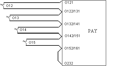
Standard wiring:
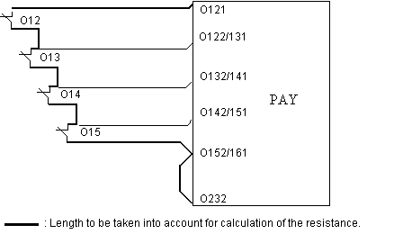
Optimized length wiring:


