Reflex function block: Type 2 command-check
(Original Document)
Role
This function is used to:
Structure
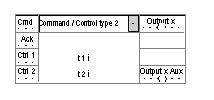
The table below shows the block's different interfaces.
Name
Meaning
Illustration
Cde
Command input.
Ctrl n
Control n input
Acq
Acknowledgement of fault.
x
Block's physical output.
x Aux
Block's internal auxiliary output.
Operation
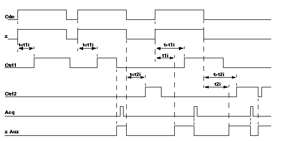
This table describes the different operating phases of the type 2 command-check function.
Phase
Description
1
On the rising edge of input Cde:
  • time-out t1i is launched,
  • input x changes to 1.
2
When time out t1i is over:
  • if the Ctrl1 signal changes to status 1 during time-out interval t1i, the x Aux input stays at 0 (normal situation),
  • if the Ctrl1 signal is not received, the x Aux output changes to 1 (type A error signal).
  • if the Ctrl1 signal falls back while the Cde input is at 1, the x Aux output changes to 1 (type B error signal).
The x Aux input is set to 0 in the event of:
  • a rising edge on input Acq with input Ctrl1 at 1,
  • change of status of input Cde.
3
On the falling edge of input Cde:
  • time-out t2i is launched,
  • input x changes to 0.
4
When time out t2i is over:
  • if the Ctrl2 signal changes to status 1 during time-out interval t2i, the x Aux input stays at 0 (normal situation),
  • if the Ctrl2 signal is not received, the x Aux output changes to 1 (type A error signal).
  • if the Ctrl2 signal falls back while the Cde input is at 0, the x Aux output changes to 1 (type B error signal).
The x Aux input is set to 0 in the event of:
  • a rising edge on input Acq with input Ctrl2 at 1,
  • change of status of input Cde.
Illustration
The illustration below shows the trend diagram of the type 2 command-check function block.