Reflex function block: Speed monitoring
(Original Document)
Role
This function is used to control or halt an action according to two thresholds t1i and t2i.
Structure
The table below shows the block's different interfaces.
Name
Meaning
Illustration
E
Enable function input.
FB
Control input.
x
Block's physical output.
x Aux
Speed control output.
Application example
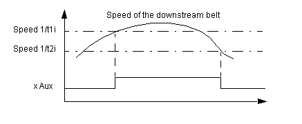
Activation of a conveyor belt upstream (controlled by the x Aux input) depending on the speed of a conveyor belt downstream:
This involves analyzing the time elapsed between 2 consecutive pulses on control input FB.
The following graph illustrates the application example given above.
Operation
This table describes the different operating phases of the speed monitoring function.
Phase
Description
1
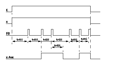
On the rising edge of input E :
  • time-out t1i is launched,
  • input x changes to 1.
2
As long as the interval between 2 rising edges of input FB remains greater than t1i:
  • time-out t1i is relaunched on the rising edge of input FB.
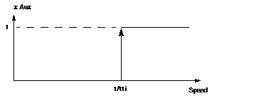
If the interval between 2 rising edges of input FB falls below t1i:
  • output x Aux changes to 1,
  • time-out t2i is launched,
If input E changes to 0, outputs x and x Aux change to 0.
3
As long as the interval between 2 rising edges of input FB is less than t2i:
  • time-out t2i is relaunched on the rising edge of input FB.
If the interval between 2 rising edges of input FB becomes greater than t2i:
  • output x Aux changes to 0,
  • time-out t1i is launched (see phase),
If input E changes to 0, outputs x and x Aux change to 0.
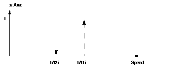
Note: The operation defined above implies that t2i >t1i.
Illustration
The illustration below shows the trend diagram of the speed monitoring function block.