

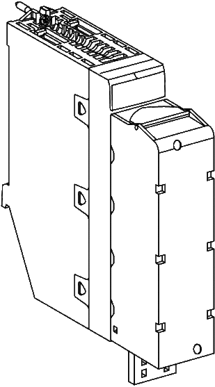
At a Glance
The BMX DAI 1614 and BMX DAI 16142 modules are fitted with a removable 40-pin terminal block for the connection of 16 input channels.
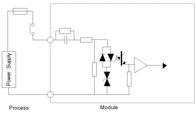
Input Circuit Diagram
The following diagram shows the circuit of an alternating current input.
Module Connection
| DANGER | |
|---|---|
| CAUTION | |
|---|---|
The following diagram shows the connection of the sensors to the module.
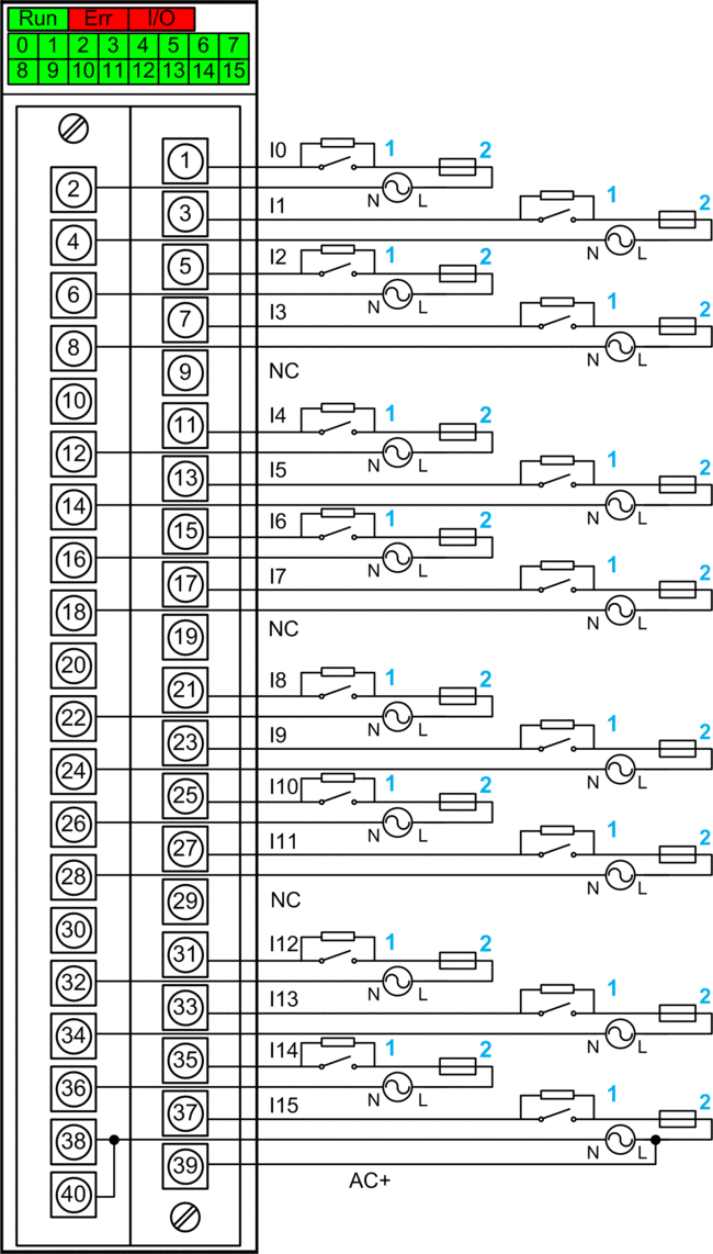
1 External resistor for open wire detection function (see detail below)
2 fast blow fuse of 0.25A
AC+ Input pin for IO supply monitoring function on channel 15 (see detail below)
NC not connected
Power supply: 100...120 Vac
Open Wire Detection Function
The open wire detection function indicates the open wire error by detecting the leakage current of the sensor. The detection threshold values are given in the general characteristics table.
If the leakage current of the sensor (at OFF state) is less than the OK threshold value (0.3 mA), then the open wire error might be reported even if the wire is not open. In order to avoid this, an external resistor is required to be added in parallel with the sensor. Refer to the module connection.
The recommended value for the external shunt resistor is 200 kΩ (1 W).
Anyhow the maximum and minimum allowed for the external resistor can be calculated according the following method:
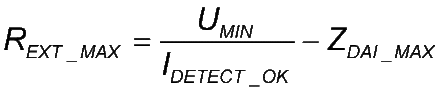
UMIN is 85% of the nominal voltage according to IEC norm.
IDETECT_OK = 0.3 mA
ZDAI_MAX = 17 kΩ (for 47 Hz) or 14 kΩ (for 57 Hz)
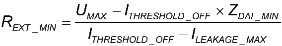
UMAX is 110% of the nominal voltage according to the IEC norm.
ITHRESHOLD_OFF = 1 mA (this is the maximum threshold current for digital input channel at 0).
ZDAI_MIN = 14 kΩ (for 53 Hz) or 12 kΩ (for 63 Hz)
ILEAKAGE_MAX is the maximum leakage current of the sensor at OFF state.
If the external resistor value is greater than the maximum calculated resistance REXT_MAX, the open wire error might be reported even if the wire is not open.
If the external resistor value is less than the minimum calculated resistance REXT_MIN, the corresponding digital input channel might see sensor state at 1 even if the sensor state is 0.
If the supply monitoring function is active and there is a loss of IO power supply, the open wire detection fault is not refreshed in Control Expert.
Supply Monitoring Function
The BMX DAI 1614 and BMX DAI 16142 modules are a channel-to-channel isolated module, 16 channels get 16 common pins.
The module terminal block has only one supply monitor input (AC+) and its common pin is shared with the channel 15.
To extend the supply monitoring function to other channels, the common of the channel 15 needs to be connected to the common pins of the other channels. In consequence the channel-to-channel isolation will be given up.
By default the supply monitoring function is inactive. Refer to the chapter Configuration for detailed information.
The IO supply state is monitored as follows:
When the IO supply is higher than 85 Vac, the EXT_PS_FLT bit is at 0 which means IO power supply is ok.
When the IO supply is lower than 40 Vac, the EXT_PS_FLT bit is at 1 which means a detected error on IO power supply. All channel input values are forced to 0.