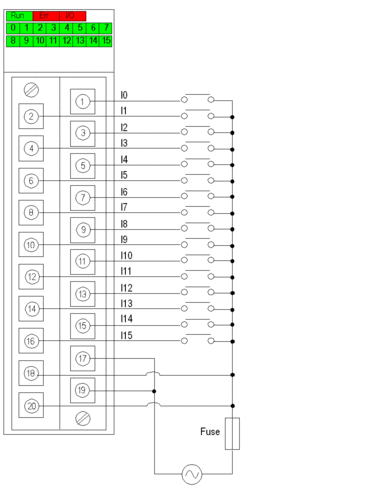
At a Glance
The BMX DAI 1602 module is fitted with a removable 20-pin
terminal block for the connection of sixteen input channels.
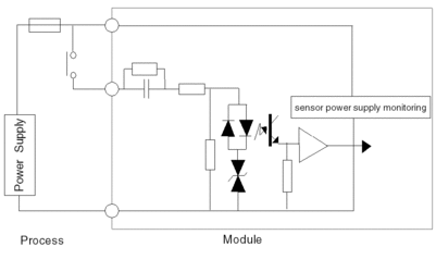
Input Circuit Diagram
The following diagram shows the circuit of an alternating
current input.
Module Connection (AC Power Supply)
| DANGER |
|---|
| HAZARD OF ELECTRICAL SHOCK, EXPLOSION OR ARC FLASH Switch off the sensor and pre-actuator voltage before
connecting or disconnecting the module. Failure to follow these instructions will result in death or serious injury. |
| CAUTION |
|---|
| LOSS OF OUTPUT FUNCTION Install the correct rating and type of fuse. Failure to follow these instructions can result in injury or equipment damage. |
The following diagram shows the connection of the module to
the sensors, using an AC power supply.
power supply: 24 VAC
fuse: fast blow fuse of 0.5A
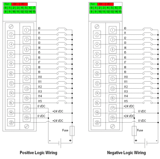
Module Connection (DC Power Supply)
This module can also be used with 24 VDC, with positive or negative
logic.
| DANGER |
|---|
| HAZARD OF ELECTRICAL SHOCK, EXPLOSION OR ARC FLASH Switch off the sensor and pre-actuator voltage before
connecting or disconnecting the module. Failure to follow these instructions will result in death or serious injury. |
| CAUTION |
|---|
| LOSS OF OUTPUT FUNCTION Install the correct rating and type of fuse. Failure to follow these instructions can result in injury or equipment damage. |
The following diagram shows the connection of the module to
the sensors, using a DC power supply.
power supply: 24 VDC
fuse: fast blow fuse of 0.5A