At a Glance
The discrete input/output modules are powered by the bus of the rack. The modules may be handled without turning off power supply to the rack, without damage or disturbance to the PLC.
Fitting operations (installation, assembly and disassembly) are described below.
Installation Precautions
The Modicon X80 discrete modules may be installed in any of the positions in the rack except:
the positions reserved for the rack power supply modules (marked PS, PS1, and PS2),
the positions reserved for extended modules (marked XBE),
the positions reserved for the CPU in the main local rack (marked 00 or marked 00 and 01 depending on the CPU),
the positions reserved for the (e)X80 adapter module in the main remote drop (marked 00).
Power is supplied by the bus at the bottom of the rack (3.3 V and 24 V).
Before installing a module, you must take off the protective cap from the module connector located on the rack.
| DANGER | |
|---|---|
Installation
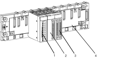
The diagram below shows some discrete input/output modules mounted on the rack.

The following table describes the different elements which make up the assembly below.
Number |
Description |
|---|---|
1 |
20-pin terminal block module |
2 |
40-pin connector module |
3 |
2 x 40-pin connector module |
4 |
Standard rack |
Installing the Module on the Rack
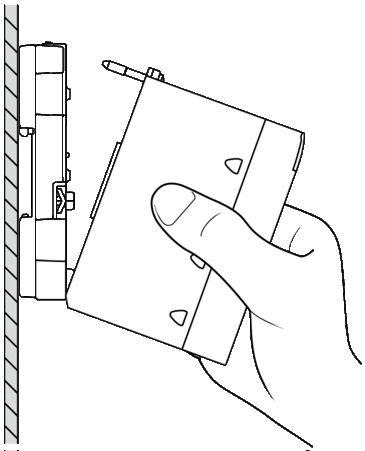
The table below presents the procedure for mounting the discrete input/output modules on the rack:
Step |
Action |
|
|---|---|---|
1 |
Remove the protective cover from the connector of the module slot on the Modicon X80 rack. |
|
2 |
Position the locating pins situated at the rear of the module (on the bottom part) in the corresponding slot in the rack. |
 |
3 |
Swivel the module towards the top of the rack so that the module sits flush with the back of the rack. |
|
4 |
Tighten the mounting screw on top of the module to hold in place on the rack. Tightening torque: 0.4...1.5 N•m (0.30...1.10 lbf-ft). |
|
| WARNING | |
|---|---|


