At a Glance
The discrete I/O modules are equipped with a display block featuring LEDs that displays the module’s channels status the overall module status.
Illustration
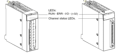
The figure below shows the position of the channel status display LEDs as well as the 3 (or 4) module status LEDs, on the front panel of the discrete I/O modules.

Description
The following table explains how the LEDs located on the discrete I/O display block operate.
LEDs |
Continually Lit |
Flashing |
Off |
|---|---|---|---|
RUN (green) |
module operating normally |
N/A |
module inoperative or off |
ERR (red) |
internal event: Module analysis needed |
Communication loss between the discrete module and the CPU |
no detected internal error |
I/O (red) |
external event: overload, short circuit, sensor/pre-actuator voltage error |
Terminal block incorrectly wired |
no detected external error |
+32 Green |
selection of channels 32 to 63 |
N/A |
selection of channels 0 to 31 |
Channel status |
channel at 1 |
channel error, overload, short circuit, or open wire detected(1) |
channel at 0 |
(1) When channel status is open wire detected, the flashing timing is the following:
|
|||
BMX DDI 1602
BMX DDI 1603
BMX DDI 1604T
BMX DDI 3202K
BMX DDI 6402K
BMX DDM 16022
BMX DDM 3202K
BMX DDM 16025
| WARNING | |
|---|---|
Display Panels
When a voltage is present on an input or output, the corresponding LED is lit.
Display of internal or external events is only effective once the module has been configured. After powering-up or a cold start, all the LEDs flash twice (for 2 seconds) to show that the module is operational. When an event is detected, the channel status is recorded until the cause of the event is cleared.
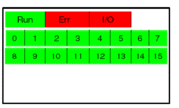
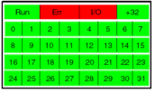
There are several display blocks depending on the type of discrete I/O module.
Modules |
Display Panel illustration |
Description |
|---|---|---|
BMX DAI 0805 BMX DAI 0814 BMX DRA 0804T BMX DRA 0805 BMX DRA 0815 BMX DRC 0805 |
 |
These modules have:
|
BMX DDI 1602 BMX DDI 1603 BMX DDI 1604T BMX DAI 1602 BMX DAI 1603 BMX DAI 1604 BMX DAI 1614 BMX DAI 1615 BMX DDO 1602 BMX DDO 1612 BMX DRA 1605 BMX DAO 1605 BMX DAO 1615 |
 |
These modules have:
|
BMX DDI 3203 BMX DDI 3232 BMX DDI 3202 K BMX DDO 3202 K BMX DDM 3202 K BMX DDM 16022(1) BMX DDM 16025(1) |
 |
These modules have:
|
BMX DDI 6402 K BMX DDO 6402 K |
 |
These modules have:
|
( 1) The BMX DDM 16022 and BMX DDM 16025 mixed input/output modules have 2 groups of 8 channels. The input group is represented by channels 0 to 7 and the output group is represented by channels 16 to 23. |
||


