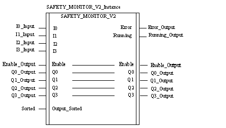
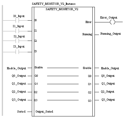
|
Description
|
|
|
(Original Document)
|


CAL SAFETY_MONITOR_V2_Instance (IO:=I0_Input, I1:=I1_Input, I2:=I2_Input, I3:=I3_Input, Enable:=Enable_Output,
Q0:=Q0_Output, Q1:=Q1_Output, Q2:=Q2_Output, Q3:=Q3_Output, Output_Sorted:=Sorted, Error=>Error_Output, Running=>Running_Output)
SAFETY_MONITOR_V2_Instance (IO:=I0_Input, I1:=I1_Input, I2:=I2_Input, I3:=I3_Input, Enable:=Enable_Output,
Q0:=Q0_Output, Q1:=Q1_Output, Q2:=Q2_Output, Q3:=Q3_Output, Output_Sorted:=Sorted, Error=>Error_Output, Running=>Running_Output);
|
Parameter
|
Type
|
Description
|
|---|---|---|
|
I0
|
Input variable 0
|
|
|
I1
|
EBOOL
|
Input variable 1
|
|
I2
|
EBOOL
|
Input variable 2
|
|
I3
|
EBOOL
|
Input variable 3
|
|
Output_Sorted
|
|
|
Parameter
|
Type
|
Description
|
|---|---|---|
|
Enable
|
|
|
|
Q0
|
EBOOL
|
Output variable 0
|
|
Q1
|
EBOOL
|
Output variable 1
|
|
Q2
|
EBOOL
|
Output variable 2
|
|
Q3
|
EBOOL
|
Output variable 3
|
|
Parameter
|
Type
|
Description
|
|---|---|---|
|
Error
|
Bit = 1: DFB or safety bus fault
(At least 1 slave faulty).
Note:
|
|
|
Running
|
EBOOL
|
Bit = 1: DFB running
|
|
Name
|
Type
|
Description
|
|---|---|---|
|
Abort
|
If this bit is set to 0 in one cycle and to 1 in the next cycle, all exchanges between the CPU and the Safety Monitor will be aborted. The DFB will reinitialize and all internal data of the DFB will be set to 0.
|
|
|
Timeout
|
Time-out during data exchange
If the DFB does not receive a correct data set before this time elapses,
|
|
|
Moni_err
|
EBOOL
|
Bit = 1: Monitor error
|
|
Out_1
|
EBOOL
|
Bit = 1: 1. OSSD (OUT1) activated
|
|
Out_2
|
EBOOL
|
Bit = 1: 2. OSSD (OUT2) activated
|
|
Device.Device_ready
|
ARRAY[0..47] OF BOOL
|
Device ready
Each index corresponds to the index of the safety device which is ready but still in test mode or waiting for another condition such as local acknowledgment, the activation of the Start button, etc.
|
|
Device.Device_off
|
ARRAY[0..47] OF BOOL
|
Device deactivated
Each index corresponds to the index of the deactivated safety device.
Note: Deactivated devices (including NOPs) set to FALSE are also transmitted as Device_off!
|
|
Device.Device_error
|
ARRAY[0..47] OF BOOL
|
Device error
Each index corresponds to the index of the faulty safety device.
|
|
Device.Device_noCom
|
ARRAY[0..47] OF BOOL
|
Device not communicating
Each index corresponds to the index of the safety device which is not communicating on the AS-i bus.
|
|
Device.Device_allocation
|
ARRAY[0..47] OF INT
|
Device receiving instruction
Each index corresponds to the index of the safety device. An integer value corresponding to the processing loop is assigned to the safety device.
Note: This information is only transmitted if Output_Sorted is set to 0!
|
|
Dfb_stat
|
STRING
|
DFB processing status in plain text
|
|
Dfb_err
|
INT
|
Indicates the following error types:
|