NOTE: The output is created with a logical AND from TRIGR and UNLOCK. Other inputs (e.g. ED) have no effect on this.
Representation: of the relevant inputs for the ACT output:
Parameterization for each diagnostics type can be found in the description for
D_LOCK,
D_ACT and
D_REA.
An individual tolerance time (DTIMEL, DTIMEA, DTIMER) can be configured for every diagnostics type.
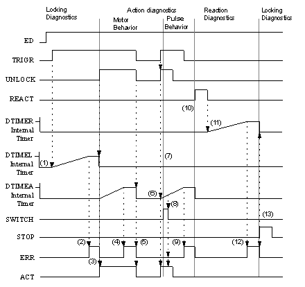
An example for the process of dynamic diagnostics is given in the timing diagram.
Timing diagram for dynamic diagnostics
(1)
The internal timer starts when TRIGR is "1" and UNLOCK is "0".
(2)
If the internal timer reaches the DTIMEL value, an error is reported.
(3)
If UNLOCK becomes "1", the error will be cancelled, the internal timer is stopped and reset, and ACT becomes "1". Activating the action switches to the action diagnostics. As the reaction has not yet occurred, the internal timer is started.
(4)
If the internal timer reaches the DTIMEA value, an error is reported.
(5)
With M behavior, when UNLOCK becomes "0", ACT becomes "0", the error will be cancelled, and the internal timer is stopped and reset.
(6)
When TRIGR and UNLOCK are "1" and REACT is "0", then ACT becomes "1" and the internal timer is started.
(7)
If SWITCH becomes "1" and ACT is "1", a switch from M behavior to I behavior occurs.
(8)
If the action diagnostics are still in progress (e.g. internal time started) during I behavior, a negative edge of the action is not significant.
(9)
If the internal timer reaches the DTIMEA value, an error is reported.
(10)
If REACT becomes "1", the internal timer is stopped and reset. Activating the reaction switches to the reaction diagnostics.
(11)
If REACT becomes "0", the internal timer is started.
(12)
If the internal timer reaches the DTIMER value, an error is reported.
(13)
If STOP becomes "1", the error will be cancelled and the internal timer is stopped and reset. An activation of the stop signal causes a switch back to locking diagnostics. 
