|
Description
|
|
|
(Original Document)
|


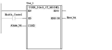
CAL User_1 (ED: = Enable_Control, COND: = Alarm_bit,
ERROR => Error_bit)
User_1 (ED: = Enable_Control, COND: = Alarm_bit,
ERROR => Error_bit);
|
Parameter
|
Type
|
Description
|
|---|---|---|
|
ED
|
DFB activation bit.
If ED = 0, theCOND input is not monitored.
|
|
|
COND
|
Bit monitored by the DFB:
|
|
Parameter
|
Type
|
Description
|
|---|---|---|
|
ERROR
|
Output indicating that the alarm is detected by the DFB.
|
|
Parameter
|
Type
|
Description
|
|---|---|---|
|
AREA_NR
|
Process zone monitored by the DFB: This zone is numbered 0 to 15 for which a zone has been determined in the Viewer.
|
|
|
OP_CTRL
|
If OP_CTRL = 1 the acknowledgement of the alarm on the Viewer is requested.
If OP_CTRL = 0 the operator does not need to acknowledge the alarm message on the Viewer.
|
|
Parameter
|
Type
|
Description
|
|---|---|---|
|
ERROR_ID
|
Variable containing the error's identifier. This unique identifier is generated automatically by the system when the REGDFB function is called (use of the ERROR_ID variable as an output parameter of the REGDFB function).
It is used on input in the DEREG function to deregister the error associated with this identifier.
|
|
|
STATUS
|
Double passworded as a parameter of the REGDFB function. When used, this double password must contain a value characteristic of the error. This status is displayed in the Viewer.
|
|
|
BUFFULL
|
BUFFULL = 1 indicates that the error was not correctly saved because the PLC's diag buffer was full.
|
|
|
PIN_NB
|
Default input number which the REGDFB function must process. This number corresponds to the order number of the inputs for which the Diag property has been selected.
In our model, the COND input is input 1 because it is the first diagnostic input. Indeed, the ED input is not used for the diagnostic.
|
|
|
PIN_VAL
|
Value expected on the PIN_NB input. In this model, the alarm is detected when COND changes to zero whereas the expected value is 1.
|