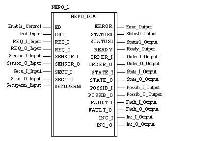
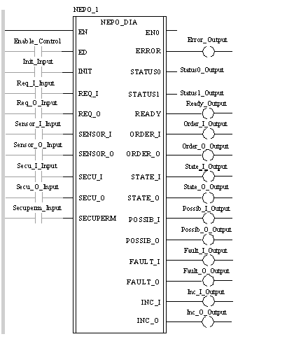
|
Description
|
|
|
(Original Document)
|


CAL NEPO_1 (ED := Enable_Control, INIT := Init_Input, REQ_I := Req_I_Input, REQ_O := Req_O_Input, SENSOR_I := Sensor_I_Input, SENSOR_O := Sensor_O_Input, SECU_I := Secu_I_Input, SECU_O := Secu_O_Input, SECUPERM := Secuperm_Input, ERROR => Error_Output, STATUS0 => Status0_Output, STATUS1 => Status1_Output, READY => Ready_Output, ORDER_I => Order_I_Output, ORDER_O => Order_O_Output, STATE_I => State_I_Output, STATE_O => State_O_Output, POSSIB_I => Possib_I_Output, POSSIB_O => Possib_O_Output, FAULT_I => Fault_I_Output, FAULT_O => Fault_O_Output, INC_I => Inc_I_Output, INC_O => Inc_O_Output,)
NEPO_1 (ED := Enable_Control, INIT := Init_Input, REQ_I := Req_I_Input, REQ_O := Req_O_Input, SENSOR_I := Sensor_I_Input, SENSOR_O := Sensor_O_Input, SECU_I := Secu_I_Input, SECU_O := Secu_O_Input, SECUPERM := Secuperm_Input, ERROR => Error_Output, STATUS0 => Status0_Output, STATUS1 => Status1_Output, READY => Ready_Output, ORDER_I => Order_I_Output, ORDER_O => Order_O_Output, STATE_I => State_I_Output, STATE_O => State_O_Output, POSSIB_I => Possib_I_Output, POSSIB_O => Possib_O_Output, FAULT_I => Fault_I_Output, FAULT_O => Fault_O_Output, INC_I => Inc_I_Output, INC_O => Inc_O_Output,);
|
Parameter
|
Type
|
Description
|
|---|---|---|
|
ED
|
DFB activation bit
When ED = 0, the DFB is not executed.
The default value is 0.
|
|
|
INIT
|
Fault acknowledgement bit
When on 1, this bit acknowledges the faults indicated by the ERROR bit and the STATUS0 word. It is reset to 0 by the DFB.
The default value is 0.
|
|
|
REQ_I,
REQ_Q
|
Request bits
These bits are set on 1 by the command part to request an "input" and "output" movement respectively.
The default value is 0.
|
|
|
SENSOR_I, SENSOR_O
|
Information input bits
These inputs receive position information from all the "input" and "output" position sensors respectively.
The default value is 0.
|
|
|
SECU_I, SECU_O
|
Safety condition
These inputs are used to link up the safety conditions of "input" and "output" movements respectively.
The default value is 0.
|
|
|
SECUPERM
|
Operating conditions.
This input is used to link up continuous operating conditions.
The default value is 0.
|
|
Parameter
|
Type
|
Description
|
|---|---|---|
|
ERROR
|
Fault bit
This bit is set on 1 as soon as a fault appears and providing that the fault has not been masked (see: Selection mask for public variables )
The default value is 0.
|
|
|
STATUS0
STATUS1
|
Fault type
These two words indicate the type of fault.
STATUS0 indicates faults linked to DFB operation.
STATUS1 is kept for configuration faults. (see:Description of NEPO_DIA and TEPO_DIA DFB status words)
The default value is 0.
|
|
|
READY
|
DFB availability
The default value is 0.
|
|
|
ORDER_I, ORDER_O
|
Activation indicator
When on 1, these bits indicate that the "input" and "output" commands have been activated respectively.
The default value is 0.
|
|
|
STATE_I, STATE_O
|
Input position
When on 1, these bits indicate that the "input" and "output" commands are being checked.
The default value is 0.
|
|
|
POSSIB_I, POSSIB_O
|
Availability indicator
These bits indicate that the DFB is ready to accept "input" and "output" movement requests respectively.
The default value is 0.
|
|
|
FAULT_I, FAULT_O
|
Fault bit
These bits indicate a constant fault during "input" and "output" movements (inoperative position) respectively.
The default value is 0.
|
|
|
INC_I, INC_O
|
Fault bit
In the absence of an order or request, these bits indicate an incoherence respectively:
The default value is 0.
|