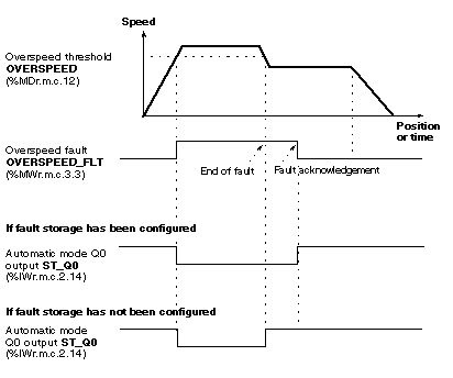
Overspeed monitoring, via a user-adjusted speed limit, enables safety action to be applied to output(s) where the overspeed limit has been exceeded (outputs are then set to 0). These outputs must be configured automatically.
The figure below shows the changes in reflex outputs following configuration (example using Q0 output).
When an output is automatic:
-
if fault storing has been configured: when a fault has disappeared, it must be acknowledged in order to reposition the output to its initial state before the fault. Acknowledging a fault prematurely has no effect.
-
if fault storing has not been configured: the disappearance of an overspeed fault repositions output to its initial state.
Note: Output in Manual Mode
Outputs in manual mode are not affected by an overspeed fault, and retain their state.
Selecting the Measurement Period
By default, the measurement period is 1 second, which can lead to an excessive delay in detecting overspeed, or insufficient precision. The measurement period can be programmed according to the speed to be monitored and precision sought:
where the precision is shown in decimal value (for example: 0.1% = 0.001) and speed in pulses/second. The sampling period is acquired in seconds.
Permissible values range from 10-2 s to 30 s.
The following table gives the minimum measurement period according to the speed to be measured, in order to guarantee precision within 0.1%.
|
Speed to be measured
(pulses/second)
|
Minimum measurement period
(s)
|
Precision
(%)
|
|
250 000 ...1 000 000
|
Greater than or equal to 10-2
|
0,1
|
|
40 000 ... 250 000
|
Greater than or equal to 25 10-3
|
0,1
|
|
10 000 ... 40 000
|
Greater than or equal to 0.1
|
0,1
|
|
1 000 ...10 000
|
Greater than or equal to 1
|
0,1
|
|
100 ...1 000
|
Greater than or equal to 10
|
0,1
|

