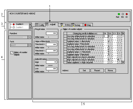
The adjustment screen displays adjustment parameters for the module and is used to modify them in both offline and on-line mode.
It also gives access to configuration and debug screens.
The structure of the adjustment screen is very similar to that of the configuration screen.
NOTE: the adjustment screen is a graphic tool for facilitating the development of a project. Unlike in configuration, it is possible to program adjustments by using language objects directly.
The diagram below shows an example of an adjustment screen.
The table below shows the different elements of the adjustment screen and their functions.
|
Number
|
Element
|
Function
|
|
1
|
Tabs
|
The foreground tab shows the mode in progress (Adjustment for this example). Each mode can be selected by means of the corresponding tab. The available modes are:
|
|
2
|
Module zone
|
Shows the abbreviated name of the module.
|
|
3
|
Channel field
|
Is used:
-
By clicking on the reference number, to display the tabs:
-
To select the channel,
-
To display the Symbol, name of the channel defined by the user (using the variable editor).
|
|
4
|
Zone general parameters
|
Is used to select the heading for setting counter outputs:
-
Function: calls up the configured counting function. This heading is fixed.
-
Task: specifies the MAST or FAST task configured. This heading is fixed.
-
Switch status: box to be checked if you wish to set latch change of status parameters. Otherwise, the heading does not appear in the adjustment field.
|
|
5
|
Adjustment field
|
This field contains various headings to be completed (parameter values), displayed according to the counting function selected.
|
Current value and initial value
For each heading two values appear:
-
the entered value which can be modified, in one window,
-
and the initial value which cannot be directly modified.
The behavior of these values depends on the PLC connection mode.
-
In offline mode: after enabling (Edit → Enable command), the entered value becomes the initial value and appears in the corresponding field. On transfer the initial value becomes the current value.
-
In on-line mode: after enabling, the entered value becomes the current value. The Services → Save parameters command is used to copy the current value in the initial value.
NOTE: the initial value is the one that the parameter concerned takes when the PLC starts from cold.
