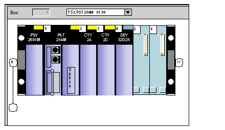
The diagram below shows the composition of the PLC.
NOTE: the CTY 2C module in position 2 is not used in this example.
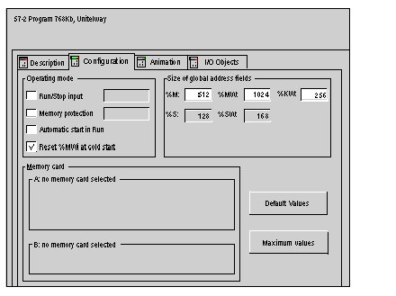
Configuration of the processor
The diagram below shows the processor configuration.
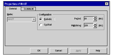
Configuration of the Mast task
The diagram below shows the configuration of the MAST task.
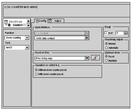
Configuration of the counting module
The diagram below shows the configuration of the counting model.
The C sensor (for counting the objects) is mated with the 0 channel.
Configuration of discrete module
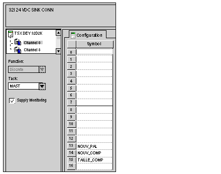
The diagram below shows the configuration of the discrete model.
The assignments of the inputs are as follows:
-
input 13: new palette forcing button (active at 1),
-
input 14: new compartment forcing button (active at 1)
-
input 15: 25/50 objects per compartment switch (1 = 50 objects).
NOTE: this module is only used for input.
Assignment of the internal bits and words
The example uses the assignments of the following internal variables:
-
%M0 : 1 starts the M motor, 0 stops it.
-
%M1 : at 1, the palette is being positioned, at 0 it is ready to receive the objects.
-
%MW0 : positions of the jack: 1,2, ,3 (corresponding to the three compartments) and 4 (for moving out the palette).
-
%MW1 : 25 or 50 (for storing the size of a palette’s compartments).
Assignment of down counting channel to the IODDT
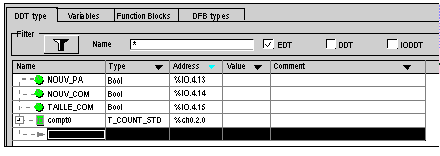
Take the IODDT T_COUNT_STD Compt0variable. The Compt0 variable is associated with channel 0 of the CTY 2A module.
The diagram below shows the variable editor.
