Physical Description
(Original Document)
Illustration
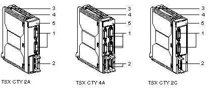
This diagram illustrates the TSX CTY 2A / 4A / 2C counting modules:
Table of numbers
This table describes the modules according to the different numbers in the diagrams above:
Number
Description
1
Standard SUB D 15-pin connector for connecting:
  • the counting sensor(s), related to channels 0 and 1 for TSX CTY 2A / 2C modules, and to channels 0, 1, 2 and 3 for TSX CTY 4A module,
  • the encoder supply when using this type of sensor,
  • the return encoder supply, which is used to check that the encoder is receiving the correct supply.
2
HE10 20-pin connectors, used for each channel to connect:
  • auxiliary inputs:
    • reset to 0 or set to the preset value,
    • count confirmation,
    • capture,
  • of auxiliary outputs,
  • external supplies:
    • auxiliary input and output supply,
    • supply of other sensors.
3
Screw for fixing module in place.
4
Rigid body, which guarantees:
  • electromagnetic card support,
  • locking of the module in its slot.
5
Module diagnostic LEDs:
  • module level diagnostics:
    • green LED RUN: indicates the operating mode of the module (operative module),
    • red LED ERR: indicates the internal state of the module (internal error, module broken down),
    • red LED I/O: indicates an external error or application fault,
  • module channel level diagnostics:
    • green CHx LED: indicates channel diagnostics.
      - LED on: channel active,
      - flashing LED: channel inactive,
      - LED off: channel inoperative, not configured or incorrectly configured.