|
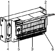
Physical description of the TELEFAST 2: ABE-7CPA11
|
|
|
(Original Document)
|

|
Number
|
Description
|
|---|---|
|
1
|
Standard 15 pin SUB-D connector for connecting the TELEFAST to the TSX CTY 2C module.
|
|
2
|
Standard 15 pin SUB-D connector for putting several TELEFASTS (maximum 4) in series.
|
|
3
|
Screw connection base for connecting one or more absolute encoders with parallel outputs (maximum 2).
The supplies can be shared out by using additional snap on connection bases: ABE-7BV10 (10 terminals) or ABE-7BV20 (20 terminals).
|
|
4
|
TELEFAST diagnostics LED. This green LED is illuminated when the TELEFAST is powered.
|
|
5
|
Protection fuse for the 10…30 V supply (rapid 1A type).
|
|
6
|
Microswitch for configuring one or more encoders (encoder number, type, etc.).
|