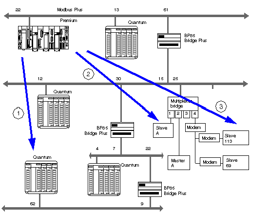
Modbus Plus addressing makes it possible to identify a device on a Modbus Plus network.
The Modbus Plus addressing system is based on the access path that needs to be followed to reach the destination device. This path is determined by the Modbus Plus routers, also referred to as Bridges Plus. So when a device has to communicate with another device, it is necessary to determine the path taken by the data to be communicated.
A Modbus Plus network segment may have up to 64 addressable devices. Each device has a unique address between 1 and 64.
Several segments may be linked by Bridges Plus.
The routing path is determined by the 5 bytes that indicate in succession the addresses of the devices that need to be crossed before arriving at the destination.
The routing system makes it possible to cross a maximum of 3 segments, in other words to allow communication between stations belonging to 5 consecutive segments.
NOTE: When not all of the 5 bytes are necessary (only one Bridge Plus crossed for example), the remaining bytes are set to 0.
The following illustration shows a multi-segment Modbus Plus structure. Three characteristic examples are used to explain Modbus Plus addressing:
The routing path to access the Quantum station is:
61, 30, 22, 62, 0.
NOTE: The final 0 is added so that the address path consists of 5 bytes.
The routing path to access slave A is as follows:
61, 25, 1, 0, 0.
NOTE: As slave A is the only slave on port 1, it is sufficient to indicate the port number and complete the path with the zeros to obtain the 5 bytes for the address path.
The routing path to access slave 113 is as follows:
61, 25, 4, 113, 0.
NOTE: When several slaves are connected to the same port, it is necessary to indicate the slave number after the port number. Do not forget to complete the address with zeros to obtain 5 bytes.
