Modbus Plus Network Statistics
The following table shows the statistics available on Modbus Plus.
You can obtain this data by running the corresponding MBP_MSTR operation (Modbus function code 8).
Word |
Bits |
Description |
|---|---|---|
00 |
Node type ID |
|
0 |
Unknown node type |
|
1 |
PLC node |
|
2 |
Modbus bridge node |
|
3 |
Host computer node |
|
4 |
Bridge Plus node |
|
5 |
Peer I/O node |
|
6 ... 15 |
Reserved |
|
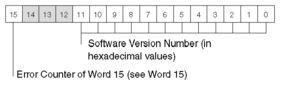
01 |
0 ... 11 |
Software version number as hexadecimal value (to read this, isolate bits 12-15 from the word) |
12 ... 14 |
Reserved |
|
15 |
Defines error counters from word 15. The most significant bit defines the use of error counters
in word 15. The lower valued half of the most significant byte together
with the least significant byte contain the software version. |
|
02 |
Network address of this station |
|
03 |
MAC status variable: |
|
0 |
Startup status |
|
1 |
Offline status indicator signals |
|
2 |
Duplicated offline status |
|
3 |
Idle status |
|
4 |
Token utilization status |
|
5 |
Work response status |
|
6 |
Token transfer status |
|
7 |
Response request status |
|
8 |
Status check of transfer |
|
9 |
Token request status |
|
10 |
Response request status |
|
04 |
Peer status (LED code); indicates status of this device relative to the network: |
|
0 |
Monitor connect operation |
|
32 |
Normal connect operation |
|
64 |
Never receives token |
|
96 |
Single station |
|
128 |
Duplicate station |
|
05 |
Token transfer counter; increments each time this station receives the token |
|
06 |
Token cycle time in ms |
|
07 |
LOW |
Bit representation data master fail during token ownership |
HIGH |
Bit representation (bitmap) program master fail during token ownership |
|
08 |
LOW |
Bitmap activity token ownership of the data master |
HIGH |
Bitmap activity token ownership of the program master |
|
09 |
LOW |
Bitmap activity token ownership of the data slave |
HIGH |
Bitmap activity token ownership of the program slave |
|
10 |
LOW |
|
HIGH |
Bitmap transfer request command data slave/slave poll |
|
11 |
LOW |
Bitmap response transfer request program master/master poll |
HIGH |
Bitmap transfer request command program slave/slave poll |
|
12 |
LOW |
Bitmap connect status of the program master |
HIGH |
Bitmap automatic log-off of program slave |
|
13 |
LOW |
Pretransfer delay error counter |
HIGH |
Receive buffer DMA overrun error counter |
|
14 |
LOW |
Receive counter repeat command |
HIGH |
Error counter data block size |
|
15 |
If bit 15 of word 1 = 0, word 15 has the following significance: |
|
LOW |
Error counter receiver collision abort |
|
HIGH |
Error counter receiver alignment |
|
If bit 15 of word 1 = 1, word 15 has the following significance: |
||
LOW |
Data block error on cable A |
|
HIGH |
Data block error on cable B |
|
16 |
LOW |
Error counter CRC receiver |
HIGH |
Error counter wrong packet length |
|
17 |
LOW |
Error counter wrong link address |
HIGH |
Error counter DMA underflow transfer buffer storage |
|
18 |
LOW |
Error counter wrong internal packet length |
HIGH |
Error counter wrong MAC function code |
|
19 |
LOW |
Communication retry counter |
HIGH |
Error counter communication failed |
|
20 |
LOW |
Counter package receipt successful |
HIGH |
Error counter no response receipt |
|
21 |
LOW |
Error counter unexpected response receipt |
HIGH |
Error counter unexpected path |
|
22 |
LOW |
Error counter unexpected response |
HIGH |
Error counter skipped transaction |
|
23 |
LOW |
Bitmap active station table, nodes 1 through 8 |
HIGH |
Bitmap active station table, nodes 9 through 16 |
|
24 |
LOW |
Bitmap active station table, nodes 17 through 24 |
HIGH |
Bitmap active station table, nodes 25 through 32 |
|
25 |
LOW |
Bitmap active station table, nodes 33 through 40 |
HIGH |
Bitmap active station table, nodes 41 through 48 |
|
26 |
LOW |
Bitmap active station table, nodes 49 through 56 |
HIGH |
Bitmap active station table, nodes 57 through 64 |
|
27 |
LOW |
Bitmap token station table, nodes 1 through 8 |
HIGH |
Bitmap token station table, nodes 9 through 16 |
|
28 |
LOW |
Bitmap token station table, nodes 17 through 24 |
HIGH |
Bitmap token station table, nodes 25 through 32 |
|
29 |
LOW |
Bitmap token station table, nodes 33 through 40 |
HIGH |
Bitmap token station table, nodes 41 through 48 |
|
30 |
LOW |
Bitmap token station table, nodes 49 through 56 |
HIGH |
Bitmap token station table, nodes 57 through 64 |
|
31 |
LOW |
Bitmap table regarding existence of global data, nodes 1 through 8 |
HIGH |
Bitmap table regarding existence of global data, nodes 9 through 16 |
|
32 |
LOW |
Bitmap table regarding existence of global data, nodes 17 through 24 |
HIGH |
Bitmap table regarding existence of global data, nodes 25 through 32 |
|
33 |
LOW |
Bitmap table regarding existence of global data, nodes 33 through 40 |
HIGH |
Bitmap table regarding existence of global data, nodes 41 through 48 |
|
34 |
LOW |
Bitmap table regarding existence of global data, nodes 49 through 56 |
HIGH |
Bitmap table regarding existence of global data, nodes 57 through 64 |
|
35 |
LOW |
Bitmap receive buffer used, buffers 1 through 8 |
HIGH |
Bitmap receive buffer used, buffers 9 through 16 |
|
36 |
LOW |
Bitmap receive buffer used, buffers 17 through 24 |
HIGH |
Bitmap receive buffer used, buffers 25 through 32 |
|
37 |
LOW |
Bitmap receive buffer used, buffers 33 through 40 |
HIGH |
Counter of activated processed commands for station administration |
|
38 |
LOW |
Counter activation command output path 1 of the data master |
HIGH |
Counter activation command output path 2 of the data master |
|
39 |
LOW |
Counter activation command output path 3 of the data master |
HIGH |
Counter activation command output path 4 of the data master |
|
40 |
LOW |
Counter activation command output path 5 of the data master |
HIGH |
Counter activation command output path 6 of the data master |
|
41 |
LOW |
Counter activation command output path 7 of the data master |
HIGH |
Counter activation command output path 8 of the data master |
|
42 |
LOW |
Counter command processing input path 41 of the data slave |
HIGH |
Counter command processing input path 42 of the data slave |
|
43 |
LOW |
Counter command processing input path 43 of the data slave |
HIGH |
Counter command processing input path 44 of the data slave |
|
44 |
LOW |
Counter command processing input path 45 of the data slave |
HIGH |
Counter command processing input path 46 of the data slave |
|
45 |
LOW |
Counter command processing input path 47 of the data slave |
HIGH |
Counter command processing input path 48 of the data slave |
|
46 |
LOW |
Counter command activation output path 81 of the program master |
HIGH |
Counter command activation output path 82 of the program master |
|
47 |
LOW |
Counter command activation output path 83 of the program master |
HIGH |
Counter command activation output path 84 of the program master |
|
48 |
LOW |
Counter command activation output path 85 of the program master |
HIGH |
Counter command activation output path 86 of the program master |
|
49 |
LOW |
Counter command activation output path 87 of the program master |
HIGH |
Counter command activation output path 88 of the program master |
|
50 |
LOW |
Counter command processing input path C1 of the program slave |
HIGH |
Counter command processing input path C2 of the program slave |
|
51 |
LOW |
Counter command processing input path C3 of the program slave |
HIGH |
Counter command processing input path C4 of the program slave |
|
52 |
LOW |
Counter command processing input path C5 of the program slave |
HIGH |
Counter command processing input path C6 of the program slave |
|
53 |
LOW |
Counter command processing input path C7 of the program slave |
HIGH |
Counter command processing input path C8 of the program slave |
|