

Summary
The structure
of the MBP_MSTR control block varies according to
the type of network you are using. Structures for Modbus Plus, TCP/IP
Ethernet, and SyMax Ethernet are described below.
Control Block for Modbus Plus
Register |
Contents |
|---|---|
CONTROL[1] |
Indicates an operation that is valid for Modbus Plus |
CONTROL[2] |
Indicates the error status |
CONTROL[3] |
Indicates the length, i.e., the number of data units transferred (max. 100) |
CONTROL[4] |
Indicates |
CONTROL[5] |
Routing register 1: used to specify a destination node during network transfer (routing path addresses one of five) Most significant byte: source node address, i.e., the slot for the Modbus Plus Network Options Module (NOM) When using the Modbus Plus Port on the CPU, this byte must be set to 0 (regardless of the CPU slot). Least significant byte: destination node address, i.e., a value that represents a direct or a bridge address. If there is no bridge, this value contains the destination node address. If there is a bridge, this value contains the address of the bridge. If the NOM is inserted in slot 7 on the module rack, the most significant byte of routing register 1 looks as follows (value 0x0706):  Most significant byte Slots 1 ... 16 Least significant byte Destination address (binary value between 1 and 64 (normal) or 65 to 255 (extended)) |
CONTROL[6] |
Routing register 2, the destination node address (further bridge or Modbus Plus modules). If addressing in the previous routing register has finished, the value is set to 0. |
CONTROL[7] |
Routing register 3, similar to routing register 2 |
CONTROL[8] |
Routing register 4, similar to routing register 2 (see Routing Register 2) |
CONTROL[9] |
Routing register 5, similar to routing register 2 (see Routing Register 2) |
Control Block for TCP/IP Ethernet
Register |
Contents |
|---|---|
CONTROL[1] |
Indicates an operation that is valid for TCP/IP |
CONTROL[2] |
Indicates the error status |
CONTROL[3] |
Indicates the length, i.e., the number of data units transferred (max. 100) |
CONTROL[4] |
Indicates |
CONTROL[5] |
Routing register: used to specify a destination node during network transfer Most significant byte: source node address, i.e., the NOE slot for the NOE module When using an integrated Ethernet on the CPU, this byte must be set to 254 (FE hex) regardless of the CPU slot. Least significant byte: destination node address, i.e, a value that represents a direct or bridge address. If there is no bridge the value in the least significant byte is set to 0. If there is a bridge, this value contains the MBP for the Ethernet mapping index (MET). If the NOE is inserted in slot 7 on the module rack and the Ethernet mapping index (MET) is 6, the routing register looks as follows (value 0x0706):  Most significant byte Slots 1 ... 16 Least significant byte MBP on Ethernet Transporter (MET) mapping index |
CONTROL[6] |
Byte 4, MSB of the 32-bit destination IP address |
CONTROL[7] |
Byte 3 of the 32-bit destination IP address |
CONTROL[8] |
Byte 2 of the 32-bit destination IP address |
CONTROL[9] |
Byte 1, LSB of the 32-bit destination IP address |
CONTROL[10] |
Indicates |
CONTROL[11] |
Indicates |
Control Block for SY/MAX Ethernet
Register |
Contents |
|---|---|
CONTROL[1] |
Indicates an operation that is valid for SY/MAX |
CONTROL[2] |
Indicates the error status |
CONTROL[3] |
Indicates the length, i.e., the number of registers transferred (max. 100) |
CONTROL[4] |
Indicates |
CONTROL[5] |
Routing register: used to specify a destination node during network transfer Most significant byte: source node address, ie.e, the slot for the NOE module Least significant byte: destination node address, i.e, a value that represents a direct or bridge address. If there is no bridge the value in the least significant byte is set to 0. If there is a bridge, this value contains the MBP for the Ethernet mapping index (MET). If NOM is inserted in slot 7 on the module rack and the Ethernet mapping index (MET) is 6, the routing register looks as follows (value 0x0706): 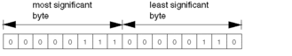 Most significant byte Slots 1 ... 16 Least significant byte MBP on Ethernet Transporter (MET) mapping index |
CONTROL[6] |
Destination drop number (or set to FF hex) |
CONTROL[7] |
Terminator (set to FF hex) |