Description
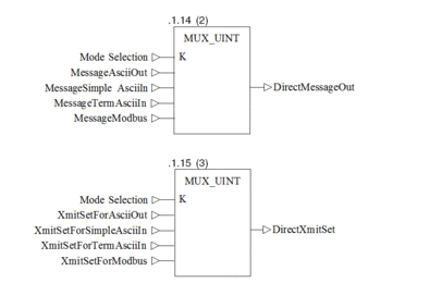
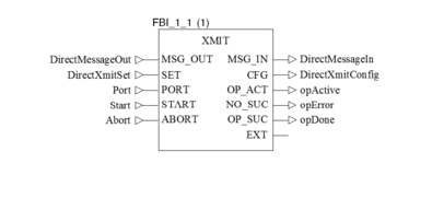
The following program is a short demo application which allows to easily switch between the four main functions of the XMIT block:
ASCII Message Out (0)
Simple ASCII In (1)
Terminated ASCII In (2)
Modbus Master (3)
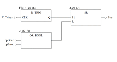
To select the function enter the appropriate number into the ModeSelection variable. A rising signal on X_Trigger activates the XMIT block by setting the Start variable 1. Start remains 1 until the function has been performed or an error occured
IEC Section
Selection of configuration data

XMIT function block

Keeps Start "on" until command finished or an error occurs

Variable Declarations
The following tables show the variables used in this example
Variable table
Variable Name |
Data Type |
Address |
Description |
|---|---|---|---|
Start |
|
Must remain ON until the XMIT has been finished |
|
Abort |
|
Aborts XMIT operation |
|
opActive |
|
Indicates XMIT Status |
|
opError |
|
Indicates XMIT Status |
|
opDone |
|
Indicates XMIT Status |
|
Port |
|
Select port 1 or 2 |
|
DirectMessageOut |
WordArr256 |
400257 |
Actual configuration data or data to be transmitted |
DirectXmitSet |
XMIT_SET |
400513 |
Actual configuration data |
DirectMessageIn |
WordArr256 |
400001 |
Data received by ASCII In functions |
DirectXmitConfig |
XMIT_CFG |
400523 |
Actual configuration data |
X_Trigger |
|
Triggers the XMIT function |
|
ModeSelection |
|
Select the requested function 0..3 |
|
Message AsciiOut |
WordArr256 |
Message to be transmitted by ASCII Out |
|
MessageSimpleAsciiIn |
WordArr256 |
(no content needed) |
|
MessageTermAsciiIn |
WordArr256 |
Configuration data for Terminated ASCII In |
|
MessageModbus |
WordArr256 |
Configuration data for Modbus |
|
XmitSetForAsciiOut |
XMIT_SET |
Configuration data for ASCII Out |
|
XmitSetForSimpleAsciiIn |
XMIT_SET |
Configuration data for Simple ASCII In |
|
XmitSetForTermAsciiIn |
XMIT_SET |
Configuration data for Terminated ASCII In |
|
XmitSetForModbus |
XMIT_SET |
Configuration data for Modbus |
Īnitial Values
The following tables show the initial values for the different arrays used:
Content of XmitSetForAaciiOut Data Structure
Element Name |
Data Type |
Address |
Comment |
|---|---|---|---|
BaudRate |
|
9600 |
|
DataBits |
|
8 |
|
Parity |
|
2 |
|
StopBits |
|
1 |
|
CommandWord |
|
512 |
Bit 7 set |
MessageLen |
|
16 |
Transmits the first 16 Characters from MessageAsciiOut array |
RespTimeOut |
|
100 |
|
RetryLimit |
|
100 |
|
XmStartDelay |
|
100 |
|
XmEndDelay |
|
100 |
Content of XmitSetForSimpleAsciiIn Data Structure
Element Name |
Data Type |
Address |
Comment |
|---|---|---|---|
BaudRate |
|
9600 |
|
DataBits |
|
8 |
|
Parity |
|
2 |
|
StopBits |
|
1 |
|
CommandWord |
|
1152 |
Bits 6 and 9 set |
MessageLen |
|
16 |
opDone is set to 1 after receiving 16 characters |
RespTimeOut |
|
100 |
|
RetryLimit |
|
100 |
|
XmStartDelay |
|
100 |
|
XmEndDelay |
|
100 |
Content of XmitSetForTermAsciiIn Data Structure
Element Name |
Data Type |
Address |
Comment |
|---|---|---|---|
BaudRate |
|
9600 |
|
DataBits |
|
8 |
|
Parity |
|
2 |
|
StopBits |
|
1 |
|
CommandWord |
|
2176 |
Bits 5 and 9 set |
MessageLen |
|
5 |
The DirectXmitSet.MessageLen element will be automatically set to 5 independent of this entry |
RespTimeOut |
|
100 |
|
RetryLimit |
|
100 |
|
XmStartDelay |
|
100 |
|
XmEndDelay |
|
100 |
Content of XmitSetForModbus Data Structure
Element Name |
Data Type |
Address |
Comment |
|---|---|---|---|
BaudRate |
|
9600 |
|
DataBits |
|
8 |
RTU Mode |
Parity |
|
2 |
|
StopBits |
|
1 |
|
CommandWord |
|
256 |
Bit 8 set |
MessageLen |
|
5 |
For Function Codes 01...06, 15 and 16 |
RespTimeOut |
|
1000 |
|
RetryLimit |
|
10 |
|
XmStartDelay |
|
100 |
|
XmEndDelay |
|
100 |
Content of MessageAsciiOut Data Structure
Element Name |
Data Type |
Address |
Comment |
|---|---|---|---|
MessageAsciiOut[2] |
|
17220 |
'CD' to be transmitted |
MessageAsciiOut[3] |
|
17734 |
'EF' |
MessageAsciiOut[4] |
|
18248 |
'GH' |
MessageAsciiOut[5] |
|
18762 |
'IJ' |
MessageAsciiOut[6] |
|
19276 |
'KL' |
MessageAsciiOut[7] |
|
19790 |
'MN' |
MessageAsciiOut[8] |
|
20304 |
'OP' |
MessageAsciiOut[...] |
|
... |
Content of MessageTermAsciiIn Data Structure
Element Name |
Data Type |
Address |
Comment |
|---|---|---|---|
MessageAsciiOut[1] |
|
258 |
0x0102 1 starting and 2 termination characters |
MessageAsciiOut[2] |
|
9216 |
0x2400 First starting character '$' |
MessageAsciiOut[3] |
|
3338 |
0x0D0A Termination characters [CR][LF] |
Content of MessageModbus Data Structure
Element Name |
Data Type |
Address |
Comment |
|---|---|---|---|
MessageAsciiOut[1] |
|
3 |
Read multiple holding registers (4x) |
MessageAsciiOut[2] |
|
32 |
Read 32 registers |
MessageAsciiOut[3] |
|
10 |
Slave PLC modbus address |
MessageAsciiOut[4] |
|
101 |
Start with register 40101 |
MessageAsciiOut[5] |
|
701 |
Data destination is register 40701 |


