Function Description
The ADDM function is used to convert
a character string into an address that can be used directly by the
following communication functions: READ_VAR, WRITE_VAR, INPUT_CHAR, PRINT_CHAR, DATA_EXCH, SEND_EMAIL.
The additional parameters EN and ENO can be configured.
FBD Representation

LD Representation

IL Representation
LD Addr_StringADDMST Addr_ArrayST Representation
Addr_Array := ADDM(Addr_String);Input Parameter Description
The following table describes the input parameter:
Parameter |
Type |
Comment |
|---|---|---|
|
Character string |
Device address on bus or network. |
The input is the concatenation of up to three elements that can take various values. Each element is optional:
Output port used locally to reach the target equipment: |
Target equipment |
Service to reach in the target equipment: |
|---|---|---|
NOTE: in the first case, the channel number
c is optional |
|
|
Definitions:
Netlink: network name set in the Net Link field of Ethernet channelhostAddr: IP address of the host we want to reach.r: rack number of the communication channelm: module position of the communication channelc: communication channel numbernode: Modbus or CANopen node behind a gateway (gateway identified withhostAddr)SYS: for addressing the system serverMBS: for addressing the Modbus system server (same asSYS)SMTP: for addressing theSMTPserverTCP.MBS: for addressing aTCPModbus serverCON.CIP: for addressing a connected equipment through Ethernet/IPUNC.CIP: for addressing an unconnected equipment through Ethernet/IP
r=0, m=0 and c=3.List of different use cases:
Address syntaxes |
Comment |
|---|---|
|
To access the Example: |
|
To access the Example: |
|
To access the node behind the Example: |
|
To access the Example: |
|
To access the node behind the Example: |
|
To access an equipment through
an Ethernet/IP network, the suffix Example 1: Example 2: |
|
To access the channel system of a Modbus channel or to send data through a Character Mode Link. NOTE:
c= 0 or 1.Example: |
|
To access the Modbus serial slave equipment server. NOTE:
c= 0 or 1, e=1 to 247.Example: |
Specific case for M340 CPU with
CANopen embedded: |
To access the CANopen slave NOTE:
e=1 to 127.Example: |
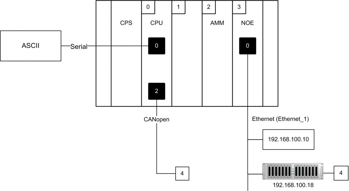
Examples with Modicon M340:

In the following examples, the third syntax element is not used:
Device to address |
ADDM syntax |
|---|---|
Device #4 on CANopen link |
|
ASCII printer on CPU serial link |
|
Device whose address is 192.168.100.10 on a NOE Ethernet link |
|
Modbus device #4 behind Ethernet gateway whose address is 192.168.100.18 on NOE Ethernet link |
|
For further information, please refer to M340 PLCs addressing overview of user manual Communication Architectures.
| CAUTION | |
|---|---|
Output Parameter Description
The following table describes the output parameter:
Parameter |
Type |
Comment |
|---|---|---|
OUT |
Array of 8 integers |
Array representing the address of a device. This parameter can be used as an input parameter for several communication functions. |
The ADDM block analyses
the addressing string syntax (parameter IN) and puts the result into
an 8 single integers array which defines the destination address.
The destination address can be provided either by the OUT parameter
of the ADDM function or directly by an array of 8 INT objects. However,
it is strongly recommended to use the ADDM function to address a communication
EF.
The destination address’ structure is as follows:
Field |
Size |
Value |
|---|---|---|
|
Byte |
Reserved. |
|
Byte |
Reserved. |
|
Byte |
Rack slot number. |
|
Byte |
Module slot number. |
|
Byte |
Channel number. |
|
Byte |
Reserved. 0 for Modbus. |
|
Byte |
This byte can have the following values:
|
|
Byte |
Device number, Modbus device for example. |
|
4 Integers |
Reserved. It is used to encode additional address information for TCP/IP addresses. |
| WARNING | |
|---|---|


