At a Glance
The example selected is a Modbus communication application via modems.
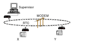
The figure below illustrates the example:

The devices communicate with each other using modems. The supervisor is Modbus master whereas the X and Y PLCs are slaves.
The goal of the example is to write the data area values of PLC X to PLC Y.
PLC X must write a data area of 41 integers starting with the %MW100 address in PLC Y from %MW100.
To do this, PLC X must become Modbus master. The Modbus address of PLC X is 9, Y is 10.
To simplify programming, the modems have been initialized with the correct parameters via a programming terminal. These parameters are stored in non-volatile memory by the AT&W commands.


