Function Description
The WRITE_VAR function is used to
write one or more language objects of the same type:
internal bits
internal words
Verify that he objects to be written are consecutive. They may be located in a remote CPU or in a device connected to a communication channel.
| WARNING | |
|---|---|
The additional parameters EN and ENO can be configured.
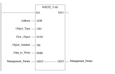
FBD Representation
Representation:

LD Representation
Representation:

IL Representation
Representation:
LD AddressWRITE_VAR Object_Type, First_Object, Object_Number, Data_to_Write, Management_ParamST Representation
Representation:
WRITE_VAR(Address, Object_Type, First_Object, Object_Number, Data_to_Write, Management_Param);Parameter Description
The following table describes the input parameters:
Parameter |
Type |
Comment |
|---|---|---|
|
ARRAY [0..5] OF ARRAY [0..7] OF |
Specific statements by hardware platforms:
|
|
|
Type of objects to write for Premium PLCs:
Type of objects to write for Modicon M340 and M580 PLCs:
|
|
|
Index of the first object to be written in the destination device. |
|
|
Number of objects to write. |
|
ARRAY [n..m] OF |
Word table containing the value of the objects to be written. |
The following table describes the input/output parameters:
Parameter |
Type |
Comment |
|---|---|---|
|
ARRAY [0...3] OF |
Exchange management table consisting of the following words:
For detailed information, refer to section Structure of the Management Parameters. |
Simultaneous Transactions
The following table gives the capacities of each communication channel to simultaneously process transactions according to various configurations on Micro and Premium PLCs.
Configuration |
Micro |
TSX 57 10 |
TSX 57 20 |
TSX 57 23/30/40/45/55, PCX 57, PMX 57 |
TSX 57 46/56 |
|---|---|---|---|---|---|
Uni-Telway master terminal port |
4 |
4 |
4 |
4 |
8 |
Uni-Telway master PCMCIA or SCY link |
1 |
8 |
8 |
8 |
8 |
Uni-Telway client slave terminal port |
4 |
1 |
1 |
1 |
8 |
Uni-Telway client slave PCMCIA or SCY link |
1 |
1 |
1 |
1 |
1 |
Uni-Telway server slave terminal port |
4 |
4 |
4 |
4 |
4 |
Uni-Telway server slave PCMCIA or SCY link |
4 |
6 |
6 |
6 |
6 |
Modbus terminal port |
4 |
- |
- |
- |
- |
Modbus PCMCIA or SCY link |
4 |
8 |
8 |
8 |
8 |
Character mode terminal block |
1 |
1 |
1 |
1 |
1 |
Character mode PCMCIA or SCY link |
4 |
8 |
8 |
8 |
8 |
CANopen PCMCIA |
- |
10 |
10 |
10 |
10 |
Fipway PCMCIA or SCY link |
4 |
8 |
8 |
8 |
8 |
Modbus Plus |
4 |
4 |
4 |
4 |
4 |
Ethernet |
- |
16 |
16 |
16 |
16 |
Embedded Ethernet |
- |
- |
- |
- |
64 |
The following table gives the capacities of each communication channel to simultaneously process transactions according to various configurations on Modicon MC80 PLCs.
Configuration |
BMKC80•03•• |
|---|---|
Embedded CANopen |
16 |
Embedded Ethernet |
16 |
Modbus master serial port |
8 |
The following table gives the capacities of each communication channel to simultaneously process transactions according to various configurations on Modicon M340 PLCs.
Configuration |
BMX P34 1000 |
BMX P34 2000 |
BMX P34 2010/ 20102 |
BMX P34 2020 |
BMX P34 2030/ 20302 |
|---|---|---|---|---|---|
Embedded CANopen |
- |
- |
16 |
- |
16 |
Embedded Ethernet |
- |
- |
- |
16 |
16 |
Modbus master serial port |
8 |
16 |
16 |
16 |
- |
Maximum number of requests as client per scan on Modicon M580 CPUs:
Configuration |
CPU Reference (BME P58 ...) |
|||||
|---|---|---|---|---|---|---|
10•0 |
20•0 |
30•0 |
40•0 |
5040 |
6040 |
|
Ethernet |
16 |
32 |
48 |
80 |
80 |
96 |
Maximum number of requests as client per scan on Hot Standby Modicon M580 CPUs:
Configuration |
CPU Reference (BME H58 ...) |
||
|---|---|---|---|
2040 |
4040 |
6040 |
|
Ethernet |
32 |
80 |
96 |
Maximum number of requests served per scan on Modicon M580 CPUs:
Configuration |
CPU Reference (BME P58 ...) |
|||||
|---|---|---|---|---|---|---|
10•0 |
20•0 |
30•0 |
40•0 |
5040 |
6040 |
|
CPU from all origin (1.) |
16 |
24 |
32 |
40 |
48 |
64 |
Embedded Ethernet |
8 |
12 |
16 |
24 (2.) |
32 |
32 |
USB |
4 |
4 |
4 |
4 |
4 |
4 |
1. %SW90 system word allows to adjust the number of requests served per cycle. The minimum number of requests served per cycle is set to 2 in order to reduce the CPU jitter. 2. Maximum number of requests is 16 for M580 CPU BME P58 40•0 with firmware version ≤ 1.20. |
||||||
Maximum number of requests served per scan on Hot Standby Modicon M580 CPUs:
Configuration |
CPU Reference (BME H58 ...) |
||
|---|---|---|---|
2040 |
4040 |
6040 |
|
CPU from all origin (1.) |
24 |
40 |
64 |
Embedded Ethernet |
12 |
24 |
32 |
USB |
4 |
4 |
4 |
1. %SW90 system word allows to adjust the number of requests served per cycle. The minimum number of requests served per cycle is set to 2 in order to reduce the CPU jitter. |
|||


