|
Starting the Application
|
|
|
(Original Document)
|


|
Step
|
Action
|
|---|---|
|
1
|
In the PLC menu, click on Standard Mode,
|
|
2
|
In the Build menu, click on Rebuild All Project. Your project is generated and is ready to be transferred to the PLC.
|
|
3
|
In the PLC menu, click on Connect. You are now connected to the PLC.
|
|
4
|
In the PLC menu, click on Transfer Project to PLC. The Transfer Project to PLC window opens. Click on Transfer. The application is transferred to the PLC.
|
|
5
|
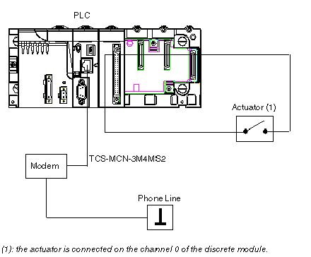
Connect the second slave PLC to a SR2MOD01 modem.
|
|
Step
|
Action
|
|---|---|
|
1
|
In the PLC menu, click on Standard Mode,
|
|
2
|
In the Build menu, click on Rebuild All Project. Your project is generated and is ready to be transferred to the PLC. When you generate the project, you will see a results window. If there is an error in the program, Control Expert indicates its location (click on the highlighted sequence).
|
|
3
|
In the PLC menu, click on Connect. You are now connected to the PLC.
|
|
4
|
In the PLC menu, click on Transfer Project to PLC. The Transfer Project to PLC window opens. Click on Transfer. The application is transferred to the PLC.
|
|
Step
|
Action
|
|---|---|
|
1
|
In the PLC, click on Run. The Run window opens. Click on OK. The application is now being executed on the PLC.
|
|
2
|
Disconnect the PC which is running Control Expert software from the first slave PLC.
|
|
3
|
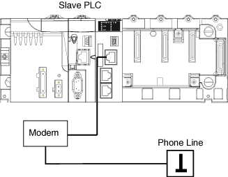
Connect the first slave PLC to a SR2MOD01 modem.
|