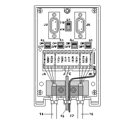
2-Wire Configuration with Data Pair Polarization via a 5VDC External Power Supply
(Original Document)
Introduction
Main cables 14 and 16 are 2-pair cables:
Power supply cable 15 is linked to an external 5VDC power supply.
Green/yellow wire 17 is connected to the module's ground terminal.
NOTE: The pair must only be polarized once on the whole bus.
Illustration
This diagram shows a configuration with shielding connection at one end only.
Position of the Switches
This table shows the switch positions.
Switches
Position On
Device Receiving Power Supply
Other Devices
S1
2W
2W
S2
OFF
OFF
S3
OFF
OFF
S4
ON
OFF
S5
OFF
OFF