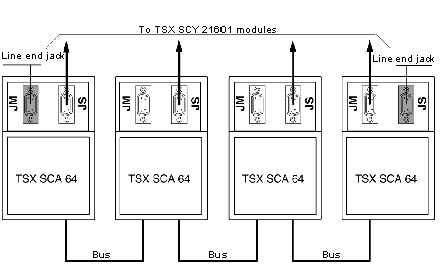
Each end of the bus cable must have a line end jack adaptor. This line end jack adapter can be plugged into free connectors on either JM (master) or JS (slave) on TSX SCA 64 devices, located at the ends of the bus.
A TSX SCA 10 kit consisting of 2 SUB D 15 pin connectors plus accessories (cover, screws, wiring etc.) enables the user to configure and set up the line end jacks.
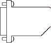
This view shows a line end jack.
This example shows a communication bus with 4 TSXx SCA 64 connection devices.
Installing Line End Jacks: At a Glance
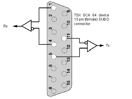
The configuration is attained by plugging each SUB D 15 pin 2-wire connector (supplied) into the sockets, enabling line adaptation.
This diagram shows the configuration:
Installation:
|
Status
|
Action
|
|
1
|
Plug the wires supplied into the SUB D 15 pin connectors as shown above.
|
|
2
|
Put the connector into place in one of the half-covers (the connector can be either way up).
|
|
3
|
Attach the latch screw.
|
|
4
|
Put the sleeve into place.
|
|
5
|
Cover it all with the other half-cover, taking care not to damage the wires.
|
|
6
|
Screw in or clip on the two half-covers (depending upon the type included).
|
|
7
|
Use the blank labels provided to show utilization.
Note: Cable clamps and/or other accessories should not be used.
|
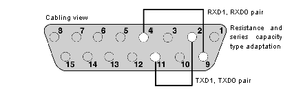
The JM or JS connectors on the TSX SCA 64 device can support a frame analyzer, which is connected by a SUB D 15 (male) pin connector. Signals relating to each pair are available on the device connectors as indicated in the diagram below.
This diagram shows the connections for different pairs of the analyzer cable.