|


|
(Original Document)
|
|
|
(Original Document)
|
|
Connection Cable
|
TER Port
|
AUX Port
|
Example of Connected Devices
|
|---|---|---|---|
|
TSX CB 1020
TSX CB 1050
|
-
|
X
|
TSX P ACC 01
|
|
T FTX CBF 020
|
X
|
X
|
FTX 517, FTX 417
|
|
TSX PCX 1031
|
X
|
-
|
FT 2100, RS 232 programming and adjustment terminals
Graphics terminals and printers managing RTS signal
Devices not handling DTE<-->DTE type RTS signals: RS 232 programming terminals, printers
|
|
XBT-Z938
|
X
|
X
|
Magelis
|
|
TSX P ACC 01
|
X
|
-
|
Connection to Uni-Telway
|
|
TSX PCX 1130
|
X
|
-
|
Devices not handling DTE<-->DCE type RTS signals: Modem
|
|
TSX PCX 3030
|
X
|
X
|
Programming and adjustment terminals with a USB port
|
|
Key:
|
|||
|
X
|
Available
|
||
|
-
|
Not available
|
||
|
Control Expert Master Uni-Telway Configuration
|
Control Expert Slave Uni-Telway Configuration
|
Control Expert Character Mode Configuration
|
|
|---|---|---|---|
|
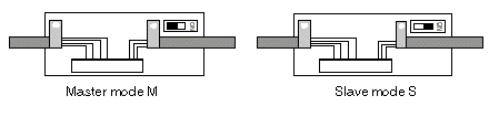
Switch position M
|
Uni-Telway Master with Control Expert configuration
|
Uni-Telway Master with default configuration
|
Uni-Telway Master with default configuration
|
|
Switch position S
|
Uni-Telway Slave with default configuration
|
Uni-Telway Slave with Control Expert configuration
|
Character Mode with Control Expert configuration
|
|
Switch Position
|
Function
|
Link in Mode
|
|---|---|---|
|
0
|
Uni-Telway PLC master communication.
|
Multi-point
|
|
1
|
Other types of communication.
|
Multi-point
|
|
2
|
Uni-Telway PLC master communication according to PLC configuration.
|
Point to point
|
|
3
|
Other types of communication according to PLC configuration.
|
Point to point
|
