Physical or logical input/output addressing
(Original Document)
At a Glance
The inputs/outputs respect the topology used by the Control Expert software and can be identified:
Topology
The addressing is defined as follows:
%
I or Q
X, W or D
r
m
c
d
.
j
Symbol
Type of object
I = input
Q = output
Format
X = boolean
W = word
D = double word
Rack address
r = 0 to 7
Position of module
m = 00 to 14
Channel No.
c = 0
Rank
d = 0 to 253
Bit j
j = 0 to 15
Physical addressing
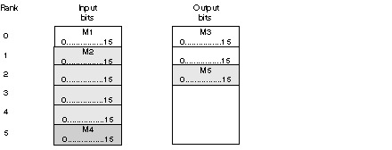
This address setting is obtained by configuring in automatic mode. The input/output words are stacked continuously according to their rank in the INTERBUS memory.
Example
Logical addressing
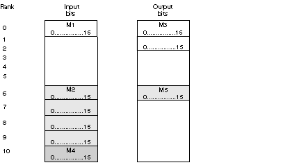
Logical addressing is carried out using CMD Tool. Its use allows the rank of I/O words to be reassigned.
This has the advantage of making it possible for the configuration to evolve through the addition of new modules, without reassigning already existing devices.
Example
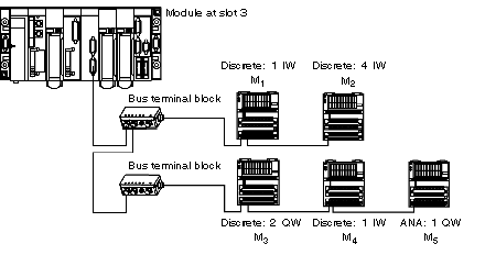
Example
The following diagram shows the physical and logical addressing.
The following table describes how to access the inputs/outputs according to their address settings.
Inputs/Outputs
Physical addressing
Logical addressing
M1: access to input 7
%IW0.3.0.0..6
%IW0.3.0.0.6
M2: access to input 24
%IW0.3.0.2.7
%IW0.3.0.7.7
M3: access to output 3
%QW0.3.0.0.2
%QW0.3.0.0.2
M4: access to input 4
%IW0.3.0.5.3
%IW0.3.0.10.3
M5: access to the analog output
%QW0.3.0.2
%QW0.3.0.6