Connection via the AUI Interface
Original instructions
General
The AUI interface is used to connect all types of devices which comply with the physical layer defined in the OSI 802.3 standard (10 BASE-5, 10 BASE-2, FOIRL, etc.) through a transceiver.
The TSX ETY 110 module can provide a remote power supply for the transceiver through the sub-D connector with the following characteristics:
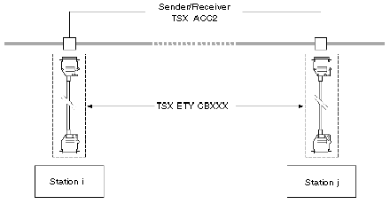
The module is connected to the main cable via a transceiver and by the following branch cables:
The maximum length of a branch may be 50 m. This length can be achieved by connecting several branch cables end to end.
NOTE: Use TSX ETH ACC2 transceivers to connect two modules point to point.
Connector Pinouts
Sub-D 15 pins according to the OSI 802.3 standard:
Pin number
ISO 802.3 Designation
Use
1
CI-S (Control In Shield)
GND
2
CI-A (Control In A)
COLL+
3
DO-A (Data Out A)
TD+
4
DI-S (Data In Shield)
GND
5
DI-A (Data in A)
RD+
6
VC (Voltage Common)
GND
7
not used
8
not used
9
CI-B (Control In B)
COLL-
10
DO-B (Data Out B)
TD-
11
DO-S (Data Out Shield)
GND
12
DI-B (Date In B)
RD-
13
VP (Voltage Plus)
12 V
14
VS (Voltage Shield)
GND
15
not used
Sub-D connector body
PG (Protective Ground)
Protective ground
Topology
Illustration:
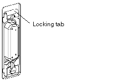
Locking Tab
The sub-D connector is equipped with a sliding lock system. The connector is locked by sliding the tab to the bottom. To ensure the module works properly in a disturbed environment, it is essential to carry out the locking procedure.