Structure display of
PI_B controller
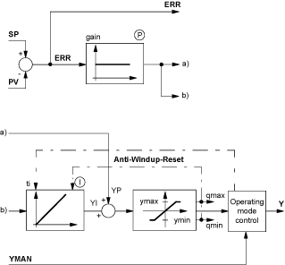
Structure of PI_B controller:
The absolute algorithm is used if no I component is available (when ti = 0). In this case the output OUT is calculated first, and the output modification will then be deducted from this.
Incremental algorithms are used when an I component is available (i.e. when ti > 0). The particularities of this algorithm are that the output alteration OUTD is calculated first and then an absolute value output is determined using the following formulas:
For this algorithm, a SERVO function block can be switched to the controller, enabling astatic control.
In addition to this the incremental algorithm offers the projection of a block-external integral component for control applications, where the actually upgraded conduct diverts from the conduct calculated by the controller (during open control cycle). In this case it is advantageous to use this for the calculation of the real value. If this is available, the RCPY input must be upgraded and the parameter en_rcpy must be switched to 1. For calculation, therefore, the equation
to
This is particularly useful for cascades or cascade-like controls.
NOTE: The output OUT is not limited for upgrading an external integral component (en_rcpy=1) .
Dead zone on deviation (
dband)
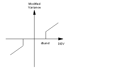
Once the work point has been reached, the dead zone is used to limit slight alignments regarding the value of the control element. as long as the deviation lies below dband (in absolute values), the calculation of the function block is based on the value zero.
Display of dead zone on deviation (dband)
The block contains the following properties:
-
The use of the parameter outbias allows for a precise setting of the work point when no integral component is available (ti = 0).
-
The output OUT is limited to the area between out_inf and out_sup for all operation modes. If a value calculated by the function block (or a written value entered by the user in manual mode) exceeds these limits, the value of OUT is capped. The incremental output OUTD, however, does not take this cut into consideration. This enables the PI_B to control a SERVO function block without having to revert the position of the control element (continuous control).
-
The choice between direct/inverse action (parameter rev_dir) allows for the adjustment of the control direction of the link control element/measuring process.
-
Limiting the setpoint between pv_inf and pv_sup.
-
The function block can operate in a purely integral mode (with kp = 0).
Function block PI_B has three operating modes: Automatic, Manual and Tracking. The tracking mode is given preference over the other operating modes.
The operating modes are selected via the inputs MAN_AUTO and TR_S.
|
Operating mode
|
TR_S
|
MAN_AUTO
|
Meaning
|
|
Automatic
|
0
|
1
|
The OUT and OUTD outputs correspond to the result of the calculations made by the function block.
|
|
Manual
|
0
|
0
|
The output OUT is not set by the function block so that the user can change the value directly.
|
|
Tracking
|
1
|
0 or 1
|
The input TR_1 is transferred to the output OUT.
|
Switching operating modes
Manual switching → automatic or tracking → automatic is carried out as follows:


