Active Pickup Sensors Wiring
Original instructions
Introduction
Use the BMXFTB2800 or BMXFTB2820 28-pin terminal blocks to connect the active pickup (APU) sensors to the module.
DANGER
HAZARD OF ELECTRIC SHOCK, EXPLOSION OR ARC FLASH
  • Ensure that the turbomachinery is stopped while connecting or disconnecting the module or the terminal block.
  • Connect or disconnect the terminal block with sensor and pre-actuator voltage switched off.
Failure to follow these instructions will result in death or serious injury.
WARNING
UNEXPECTED VALUES
Do not use incorrect APU sensor source output type to the specified input port.
Failure to follow these instructions can result in death, serious injury, or equipment damage.
The following three wires sensors can be connected to the sink type digital input. They are classified by output signal types:
Precaution
To prevent from interference, you must short wire the MPU interface when using active pickup sensor (APU). Otherwise detected interference may cause unexpected measured values.
WARNING
UNEXPECTED VALUES
Be sure to short wire the MPU interface when using active pickup sensor (APU).
Failure to follow these instructions can result in death, serious injury, or equipment damage.
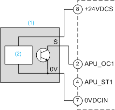
Open Collector Sink Type Wiring
Wiring example for an APU sensor on channel 1:
(1) 
Sensor with open collector sink output
(2) 
Magnetic hall effect
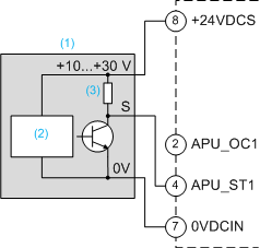
Supply Tracking Type Wiring
Wiring example for an APU sensor on channel 1:
(1) 
Sensor with supply tracking output
(2) 
Magnetic hall effect
(3) 
Generally 2 kΩ
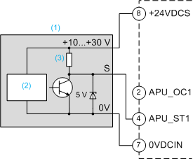
TTL Type Wiring
Wiring example for an APU sensor on channel 1:
(1) 
Sensor with TTL output
(2) 
Magnetic hall effect
(3) 
Generally 2 kΩ
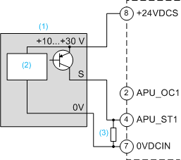
Open Collector Source Type Wiring
Wiring example for an APU sensor on channel 1:
(1) 
Sensor with open collector source output
(2) 
Magnetic hall effect
(3) 
Maximum 2 kΩ