|
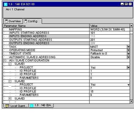
Configuration Example
|
|
|
(Original Document)
|
|
AS-i Profile
|
S1.1
|
|||
|
Bit Status
|
0
|
1
|
||
|
Data Bits
|
Status
|
D0 (Input)
|
Signal "Off"
|
Signal "On"
|
|
D1 (Input)
|
Alarm "On"
|
Alarm "Off"
|
||
|
D2 (Input)
|
Not operation ready
|
Operation ready
|
||
|
D3 (Input)
|
Not occupied
|
Not occupied
|
||
|
Command
|
D0 (Output)
|
Not occupied
|
Not occupied
|
|
|
D1 (Output)
|
Not occupied
|
Not occupied
|
||
|
D2 (Output)
|
Not occupied
|
Not occupied
|
||
|
D3 (Output)
|
Not occupied
|
Not occupied
|
||
|
Parameter
|
P0
|
Not occupied
|
Not occupied
|
|
|
P1
|
Not occupied
|
Not occupied
|
||
|
P2
|
Not occupied
|
Not occupied
|
||
|
P3
|
Flashing light "On"
|
Flashing light "Off"
|
||
|
AS-i Profile
|
S7.F
|
|||
|
Bit Status
|
0
|
1
|
||
|
Data Bits
|
Status
|
D0 (Input)
|
Not occupied
|
Not occupied
|
|
D1 (Input)
|
Not occupied
|
Not occupied
|
||
|
D2 (Input)
|
Not occupied
|
Not occupied
|
||
|
D3 (Input)
|
Not occupied
|
Not occupied
|
||
|
Command
|
D0 (Output)
|
Element 1: "off"
|
Element 1: "on"
|
|
|
D1 (Output)
|
Element 2: "off"
|
Element 2: "on"
|
||
|
D2 (Output)
|
Element 3: "off"
|
Element 3: "on"
|
||
|
D3 (Output)
|
Element 4: "off"
|
Element 4: "on"
|
||
|
Parameter
|
P0
|
Element 1: "Flashing light"
|
Element 1: "Continuous light"
|
|
|
P1
|
Element 2: "Flashing light"
|
Element 2: "Continuous light"
|
||
|
P2
|
Element 3: "Flashing light"
|
Element 3: "Continuous light"
|
||
|
P3
|
Element 4: "Flashing light"
|
Element 4: "Continuous light"
|
||

|
|
Most significant Byte
|
Least significant Byte
|
||||||||||||||
|---|---|---|---|---|---|---|---|---|---|---|---|---|---|---|---|---|
|
Word Bits
|
15
|
14
|
13
|
12
|
11
|
10
|
9
|
8
|
7
|
6
|
5
|
4
|
3
|
2
|
1
|
0
|
|
Slave Input
|
D3
|
D2
|
D1
|
D0
|
D3
|
D2
|
D1
|
D0
|
D3
|
D2
|
D1
|
D0
|
D3
|
D2
|
D1
|
D0
|
|
Word 1
|
Slave 3
|
Slave 2
|
Slave 1
|
Not Used
|
||||||||||||
|
Word 2
|
Slave 7
|
Slave 6
|
Slave 5
|
Slave 4
|
||||||||||||
|
...
|
...
|
...
|
...
|
..
|
||||||||||||
|
|
Most significant Byte
|
Least significant Byte
|
||||||||||||||
|---|---|---|---|---|---|---|---|---|---|---|---|---|---|---|---|---|
|
Word Bits
|
15
|
14
|
13
|
12
|
11
|
10
|
9
|
8
|
7
|
6
|
5
|
4
|
3
|
2
|
1
|
0
|
|
Slave Output
|
D3
|
D2
|
D1
|
D0
|
D3
|
D2
|
D1
|
D0
|
D3
|
D2
|
D1
|
D0
|
D3
|
D2
|
D1
|
D0
|
|
Word 1
|
Slave 3
|
Slave 2
|
Slave 1
|
Not Used
|
||||||||||||
|
Word 2
|
Slave 7
|
Slave 6
|
Slave 5
|
Slave 4
|
||||||||||||
|
...
|
...
|
...
|
...
|
..
|
||||||||||||