The AS-i bus is used to interconnect 31 standard address devices.
The standard address slaves each have:
-
4 input bits,
-
4 output bits,
-
4 parametering bits.
The AS-i bus can manage a maximum of 124 standard address slave Inputs and 124 Outputs.
Each slave has its own address and a profile (defines variables exchange).
AS-i is a system in which exchange management is ensured by a single master who calls in succession, by scanning the bus, each detected slave and awaits a response.
The serial communication frame transmits:
-
4 data bits (D0 to D3), which are the image of inputs or outputs according to the nature of the interface.
-
4 parametering bits (P0 to P3), which are used to set the operating modes of the interface.
P0 to P3 bits are used for "intelligent" devices, including AS-i ASIC (specific integrated circuit). Operation can be modified while it is running.
The address of the slave is coded on 5 bits.
At the request of the AS-i master, outputs are set and the inputs for AS-i devices are sent in the slave’s response.
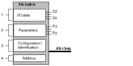
The figure below shows the structure of a standard address slave.
Description of Constituent Elements
The table below shows the different elements that make up the structure of a standard address slave.
|
Address
|
Item
|
Description
|
|
1
|
Input/output data
|
Input data is stored by the slave and made available for the AS-i master.
Output data is updated by the master module.
|
|
2
|
Parameters
|
The parameters are used to control and switch internal operating modes to the sensor or the actuator.
|
|
3
|
Configuration/Identification
|
This field contains:
-
the code which corresponds to I/O configuration,
-
the slave identification codes (ID, ID1, ID2).
|
|
4
|
Address
|
Physical address of slave.
|
|
Note: The operating parameters, address, configuration and identification data are saved in a non-volatile memory.
|
Each slave connected to the AS-i bus must have an address between 1 and 31 (coding on 5 bits).
The slaves delivered from the factory have the address 0 (the address of the slave is memorized in a non-volatile format).
Addresses are programmed using a terminal specifically for addressing, a XZMC11.
NOTE: When replacing a faulty slave whose address has been set, the address of the slave to be replaced can be updated automatically.
All slave devices connected to the AS-i bus are identified by:
-
An I/O Code (input/output distribution code).
-
An identification code, which completes the functional identification of the slave.
These identifications allow the AS-i master to recognize the configuration, which is present on the bus.
These different profiles have been developed by the AS-i Association. They are used to distinguish between input, output and mixed modules, "intelligent" device families, etc.
