Introduction to AS-i Bus Diagnostics
(Original Document)
General
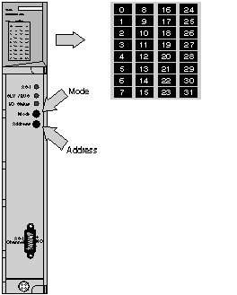
The module display panel is used for:
These modes can be accessed by a combination of actions on the push buttons "Mode" and "Address" of the 140 EIA 921 00 module.
Illustration:
Display Modes
The following table describes the 2 display modes of the module:
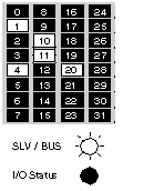
Bus mode
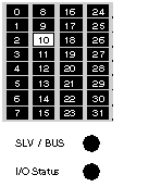
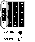
Slave mode (SLV)
View of AS-i bus image. Each LED 1 to 31 corresponds to a slave address on the bus.
  • LED on: slave present
  • flashing LED: slave projected and not detected or not projected and detected or projected, detected but not activated (I/O code or profile incorrect).
  • LED off: slave not projected and not detected.
View of selected slave address.
  • LED on: number of slave selected.
View of input/output bit state for slave selected.
  • LEDs 0 to 3 display the state of the input bits.
  • LEDs 4 to 7 display the state of the output bits.
  • LED on: bit in state 1.
  • LED off: bit in state 0 or not significant
Illustration:
The display mode is shown with the "SLV / BUS" LED on and the "I/O Status" LED off.
Illustration:
The display mode is shown with the "SLV / BUS" and "I/O Status" LEDs off.
Illustration:
The display mode is shown with the "SLV / BUS" LED off and the "I/O Status" LED on.