|
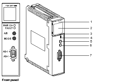
Physical description
|
|
|
(Original Document)
|

|
Number
|
Description
|
|---|---|
|
1
|
A display panel consisting of 4 LEDs for displaying the operating modes of the module:
|
|
2
|
Display panel consisting of 32 LEDs (0 to 31) which enable AS-i bus diagnostics, and display the state of each slave connected to the bus.
|
|
3
|
PWR OK LED (green): when lit, this indicates that power supply is compliant.
|
|
4
|
FAULT LED (red): when lit, this indicates faults associated with the AS-i bus.
|
|
5
|
The A/B push-button can be used to determine the state of devices on the bus by switching from bank A to B.
|
|
6
|
MODE push-button: a prolonged press on this button causes the slaves to be reset and the module to switch to OFF-LINE mode. This then allows the slaves to be programmed via an infra-red interface. The new diagnostics pocket console can also be connected to the bus. To return to normal mode, simply press the button once again for a prolonged period.
|
|
7
|
CANNON SUB D connector for connection to AS-i bus.
|