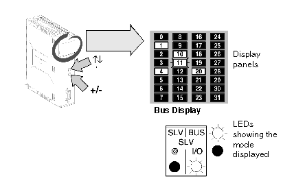
This mode is displayed by default when the module is switched on, and is used to display:
-
The expected and detected slaves (LED permanently on).
-
The unexpected and undetected slaves (LEDs off).
-
The expected and undetected slaves (LEDs flashing).
Illustration:
The image of the AS-i network is displayed on the entire display panel. Each LED represents an AS-i bus slave address.
Two LEDs "Bus" and "I/O" indicate the current display mode.
In the current example, the "BUS" LED is on and the "I/O" LED is off which indicates that the display is in Bus mode.
In the illustration above, the display panel indicates that:
-
Slaves 1, 4, 10 and 20 (LEDs on) are present.
-
Slave 11 (flashing LED) is present and not expected, or expected and missing.
