|
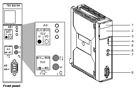
Physical description
|
|
|
(Original Document)
|

|
Number
|
Description
|
|---|---|
|
1
|
A display panel consisting of 4 LEDs for displaying the operating modes of the module:
|
|
2
|
Display panel consisting of 32 LEDs (0 to 31) which enable AS-i bus diagnostics, and display the state of each slave connected to the bus.
|
|
3
|
AS-i LED (red): when lit, this indicates an AS-i power supply fault.
|
|
4
|
Bus LED (green): when lit, this indicates that display panel2 is in BUS display mode (display of slaves on the bus).
|
|
5
|
I/O LED (green): when lit, this indicates that display panel 2 is in Slave "SLV" display mode (displays status of input/output bits for a selected slave).
|
|
6
|
Push button "↑↓" designed for local diagnostics of the AS-i bus. You can move between the different AS-i bus diagnostic modes by pressing this button (long or short presses), combined with the "+/-" push button.
|
|
7
|
Push button "+/−" designed for local diagnostics of the AS-i bus. You can move between the different AS-i diagnostics modes by pressing this button (long or short presses), combined with the "↑↓" push button.
|
|
8
|
CANNON SUB D connector for connection to AS-i bus.
|